3D pathology slide scanner

a slide scanner and pathology technology, applied in the field of microscopic imaging of large specimens, can solve the problems of increasing the chance of tiling artifacts, increasing bleaching, and slow fluorescence imaging of tiling microscopes

Inactive Publication Date: 2014-05-08
HURON TECH INT
View PDF5 Cites 47 Cited by
  • Summary
  • Abstract
  • Description
  • Claims
  • Application Information

AI Technical Summary

Benefits of technology

[0037]An instrument for scanning a large specimen, comprises a specimen holder to support the specimen, the specimen having a series of parallel object planes. The instrument has an optical system to focus an image from each object plane onto multiple linear arrays positioned on a detector image plane tilted in a scan direction such that data from each linear array comprises a different plane in a three-dimensional image of at least part of the specimen comprised of a stack of image planes. The multiple linear arrays are not tilted but are located on the image plane that is tilted relative to a scan plane and relative to the series of object planes in the specimen to enable a series of image frames of the specimen to be obtained during the scan as the specimen moves relative to an optical axis of the instrument in the scan plane.

Problems solved by technology

Such images may contain tiling artifacts, caused by focus changes between adjacent tiles, differences in illumination intensity across the field of view of the microscope, barrel or pincushion distortion near the edge of the tiles, and microscope objectives that do not have a flat focal plane.
For large specimens, thousands of tiles may be required to image the entire specimen, increasing the chance of tiling artifacts.
Tiling microscopes are very slow for fluorescence imaging.
Multiple exposure of the specimen for imaging multiple fluorophores can also increase bleaching.
Stitching tiles together is also complicated by distortion and curvature of field of the microscope objective, which occur near the edges of the field of view (just where stitching of tiles occurs).
Since exposure is adjusted by changing scan speed, it is difficult to design a strip-scanner for simultaneous imaging of multiple fluorophores, where each channel would have the same exposure time, and present strip-scanners scan one fluorophore at-a-time.
For strip-scanning instruments, estimating the exposure in advance is difficult without scanning the whole specimen first to check exposure, and this must be done for each fluorophore.
Instead of scanning first to set exposure, many operators simply set the scan speed to underexpose slightly, with resulting noisy images, or possibly images with some overexposed (saturated) areas if the estimated exposure was not correct.
When a CCD-based TDI array is used, each line image stored in memory is the result of integrating the charge generated in all of the previous lines of the array while the scan proceeds, and thus has both increased signal / noise and amplitude (due to increased exposure time) when compared to the result from a linear array detector.
It is difficult to predict the best exposure time before scanning.
Some instruments use multiple TDI detector arrays to expose and scan multiple fluorophores simultaneously, but this usually results in a final image where one fluorophore is exposed correctly and the others are either under- or over-exposed.
Linear arrays are not often used for fluorescence imaging because exposure time is inversely proportional to scan speed, which makes the scan time very long for weak fluorophores.
In addition, exposure (scan speed) must be adjusted for each fluorophore, making simultaneous measurement of multiple fluorophores difficult when they have widely different fluorescence intensity (which is common).
TDI arrays and associated electronics are expensive, but the on-chip integration of several exposures of the same line on the specimen provides the increased exposure time required for fluorescence imaging while maintaining a reasonable scan speed.
Simultaneous imaging of multiple fluorophores using multiple TDI detector arrays is still very difficult however, since each of the detectors has the same integration time (set by the scan speed), so it is common to use only one TDI array, adjusting exposure for each fluorophore by changing the scan speed and collecting a separate image for each fluorophore.
In addition, none of the prior-art scanners described above acquires a three-dimensional image of the specimen.

Method used


Image

  • 3D pathology slide scanner
  • 3D pathology slide scanner
  • 3D pathology slide scanner

Examples


first embodiment

[0057]An instrument and method for scanning microscope slides using a CCD or CMOS two-dimensional detector array that adds intermediate image frames acquired every time the microscope slide has moved an incremental distance equal to that between rows of pixels in the final image has been described in U.S. Patent Application Ser. No. 61 / 427,153, “Pathology Slide Scanner”, by A. E. Dixon. The instrument described in that application (which has not been published) has all of the advantages of a slide scanner that uses a TDI array, but uses inexpensive two-dimensional arrays instead. In addition, since the final image is the sum of a large number of intermediate image frames, each intermediate frame being displaced a distance equal to the distance between rows of pixels in the final image, it can have a larger dynamic range than that supported by the detector array, and this increased dynamic range enables multiple fluorophores to be imaged simultaneously using separate detector arrays ...

second embodiment

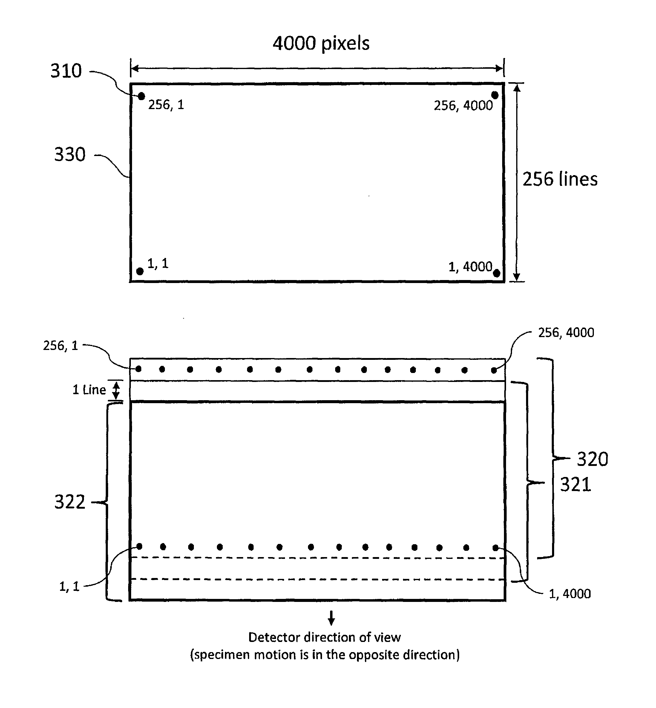
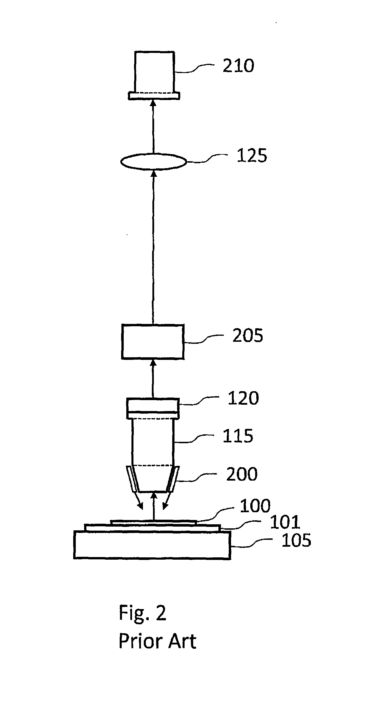
[0060]FIG. 5 shows a slide scanner for transmission imaging that is this invention. A tissue specimen 100 (or other specimen to be imaged) is mounted on microscope slide 101 (or other sample holder) on a scanning stage 105. For transmission imaging, the specimen is illuminated from below by light source 110. Microscope objective 500 (or other imaging objective) is tilted with respect to the specimen 100 and focuses light from the specimen onto two-dimensional detector array 410, which is perpendicular to optical axis 430. When focused by lens 500, light from tilted object plane 550 in specimen 100 is collected by detector pixels in image frame 520. Light from the top of specimen 100 at position 521 will be focused on a pixel in the row of pixels at position 522 on image frame 520, and light from the bottom of the specimen at position 523 will be focused on a pixel at position 524 on image plane 520. Each row of pixels in detector 410 (rows pointing into the paper in this figure) col...

third embodiment

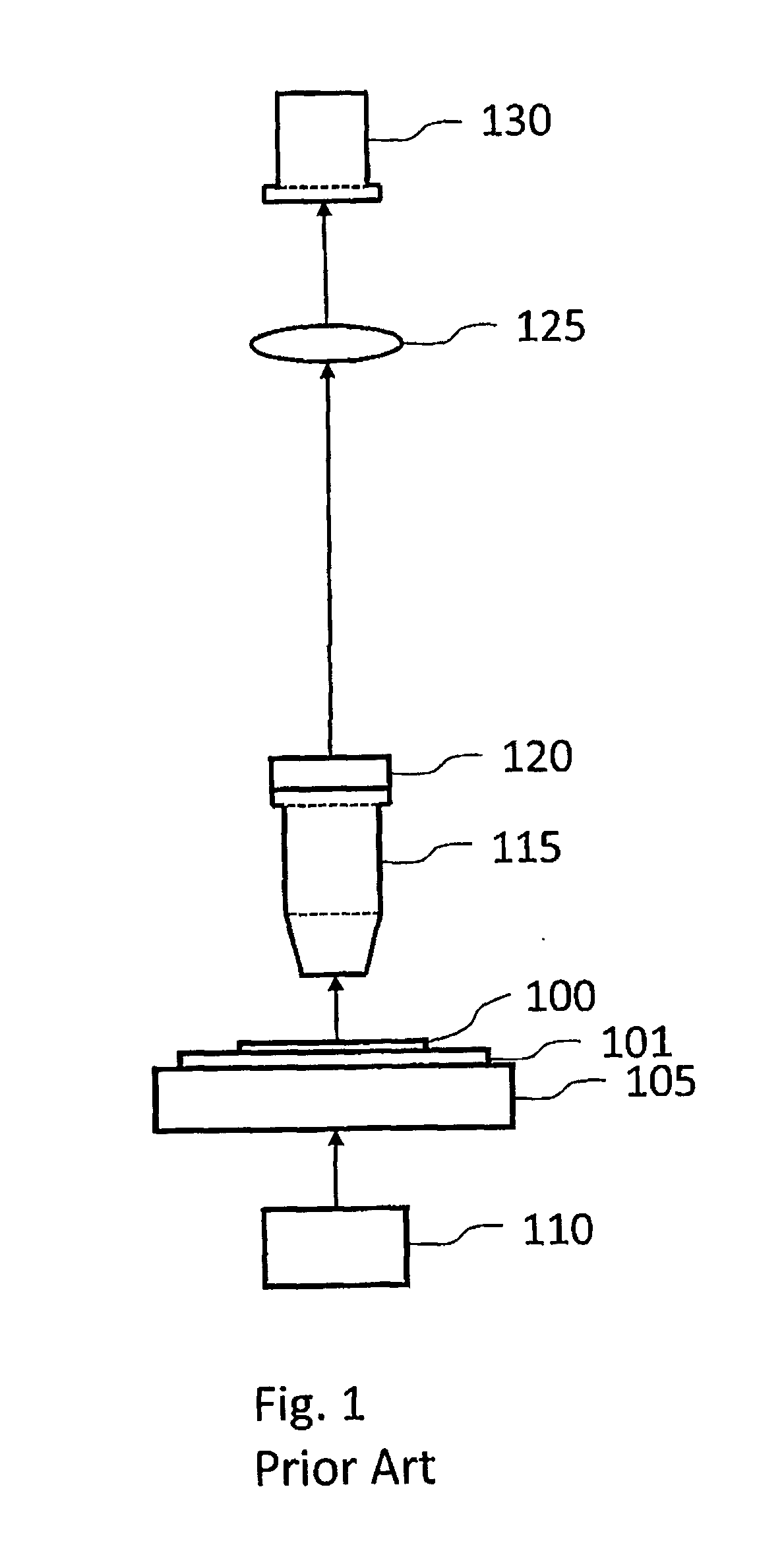
[0062]FIG. 6 shows a slide scanner for transmission imaging that is this invention (a preferred embodiment). A tissue specimen 100 (or other specimen to be imaged) is mounted on microscope slide 101 (or other sample holder) on a scanning stage 105. For transmission imaging, the specimen is illuminated from below by light source 110. A combination of infinity-corrected microscope objective 115 (or other infinity-corrected imaging objective) and tube lens 125 focuses light from the specimen onto two-dimensional detector array 410, which is tilted with respect to the plane of the microscope slide about an axis that is in the plane of the microscope slide and is perpendicular to the direction of stage motion. When focused by objective 115 and tube lens 125, light from tilted object plane 450 in specimen 100 is collected by detector pixels in image plane 420. Light from the top of specimen 100 at position 421 will be focused to a parallel beam by objective 115 (the outside of this parall...


PUM

PropertyMeasurementUnit
distanceaaaaaaaaaa
distanceaaaaaaaaaa
thickaaaaaaaaaa

Abstract

An instrument and method for scanning a large specimen comprises a specimen holder to support the specimen, an optical system to focus an image of a series of parallel object planes onto one of a two dimensional detector array, multiple linear arrays, multiple TDI arrays and multiple two-dimensional arrays. The detector array has a detector image plane that is tilted relative to the series of object planes in a scanned direction to enable a series of image frames of the specimen to be obtained in order to produce a three-dimensional image of at least part of the specimen with data from each row of the image frame representing a different plane in the three-dimensional image.

Description

BACKGROUND OF THE INVENTION[0001]1. Field of the Invention[0002]This invention relates to the field of microscopic imaging of large specimens with particular emphasis on brightfield and fluorescence imaging. Applications include imaging tissue specimens, genetic microarrays, protein arrays, tissue arrays, cells and cell populations, biochips, arrays of biomolecules, detection of nanoparticles, photoluminescence imaging of semiconductor materials and devices, and many others.[0003]2. Description of the Prior Art[0004]The macroscope originally described in U.S. Pat. No. 5,381,224 is a scanning-laser system that uses a telecentric laser-scan lens to provide a wide field of view. Several embodiments are presently in use. These include instruments for fluorescence and photoluminescence (including spectrally-resolved) imaging (several other contrast mechanisms are also possible), instruments in which a raster scan is provided by the combination of a scanning mirror and a scanning specimen...

Claims


Application Information

Patent Timeline
Patent Type & Authority Applications(United States)
IPC IPC(8): G02B21/36G01N21/59G01N21/47G01N21/64
CPCG02B21/365G01N21/64G01N21/59G01N21/47G01N21/4795G01N21/6458G02B21/367
Inventor DAMASKINOS, SAVVASCRAIG, IAN JAMESDIXON, ARTHUR EDWARD
Owner HURON TECH INT
Why Eureka
Try Eureka