

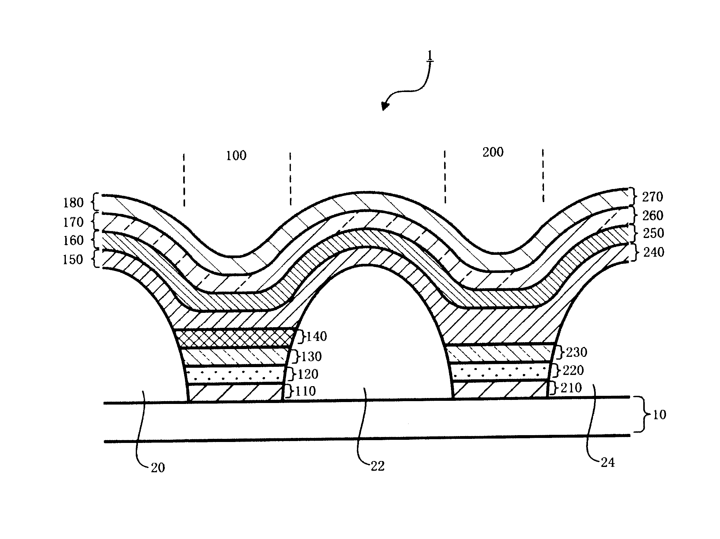
Organic el multi-color light-emitting device
a multi-color light-emitting device and organic technology, applied in the direction of electroluminescent light sources, chemistry apparatuses and processes, and compositions of light-emitting substances, can solve the problems of reduced cost, increased size, and inefficient use of materials, and achieves long life, high efficiency, and high quality.
- Summary
- Abstract
- Description
- Claims
- Application Information
AI Technical Summary
Benefits of technology
Problems solved by technology
Method used
Image

Examples
example 1
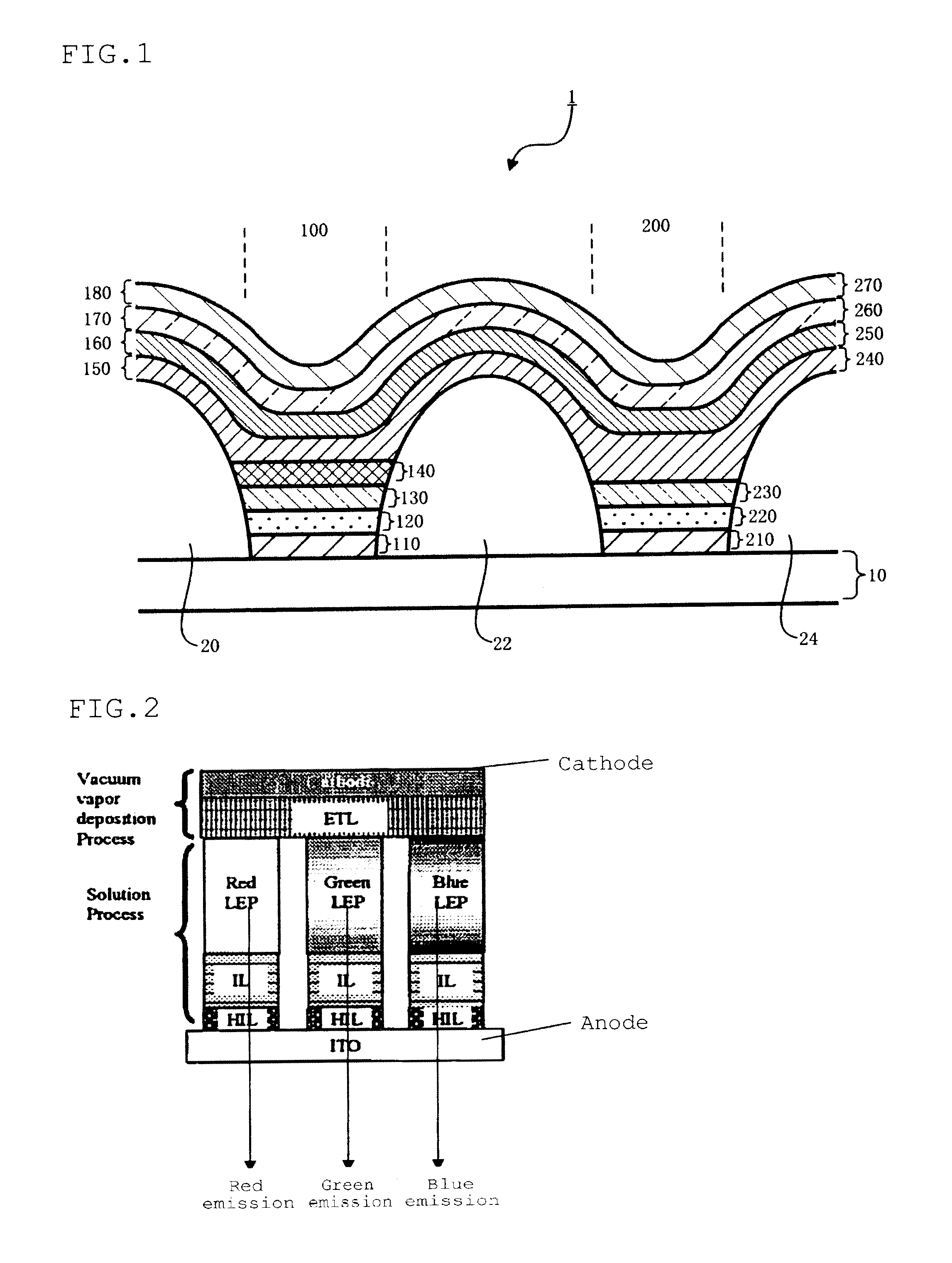
[0232]In order to confirm the effects of the organic EL multi-color emitting device of the invention, the first light-emitting element and the second light-emitting element were evaluated.
[Formation of a Second Light-Emitting Element (Blue Fluorescent Emitting Device)]
[0233]A glass substrate measuring 25 mm×75 mm×1.1 mm thick, with an ITO transparent electrode was subjected to ultrasonic cleaning in isopropyl alcohol for 5 minutes and then to UV ozone cleaning for 30 minutes. On the thus cleaned glass substrate with the transparent electrode, ND1501 (aniline oligomer manufactured by Nissan Chemical Industries, Ltd.) was formed into a 25 nm-thick film by the spin coating method. The film was heated at 230° C. to form a hole-injecting layer. Subsequently, a xylene solution (1.0 wt %) of HT1 was formed into a film of 30 nm by the spin coating method, dried at 120° C., whereby a hole-transporting layer was formed. Subsequently, as the material for the second adjacent layer (second organ...
examples 2 to 11
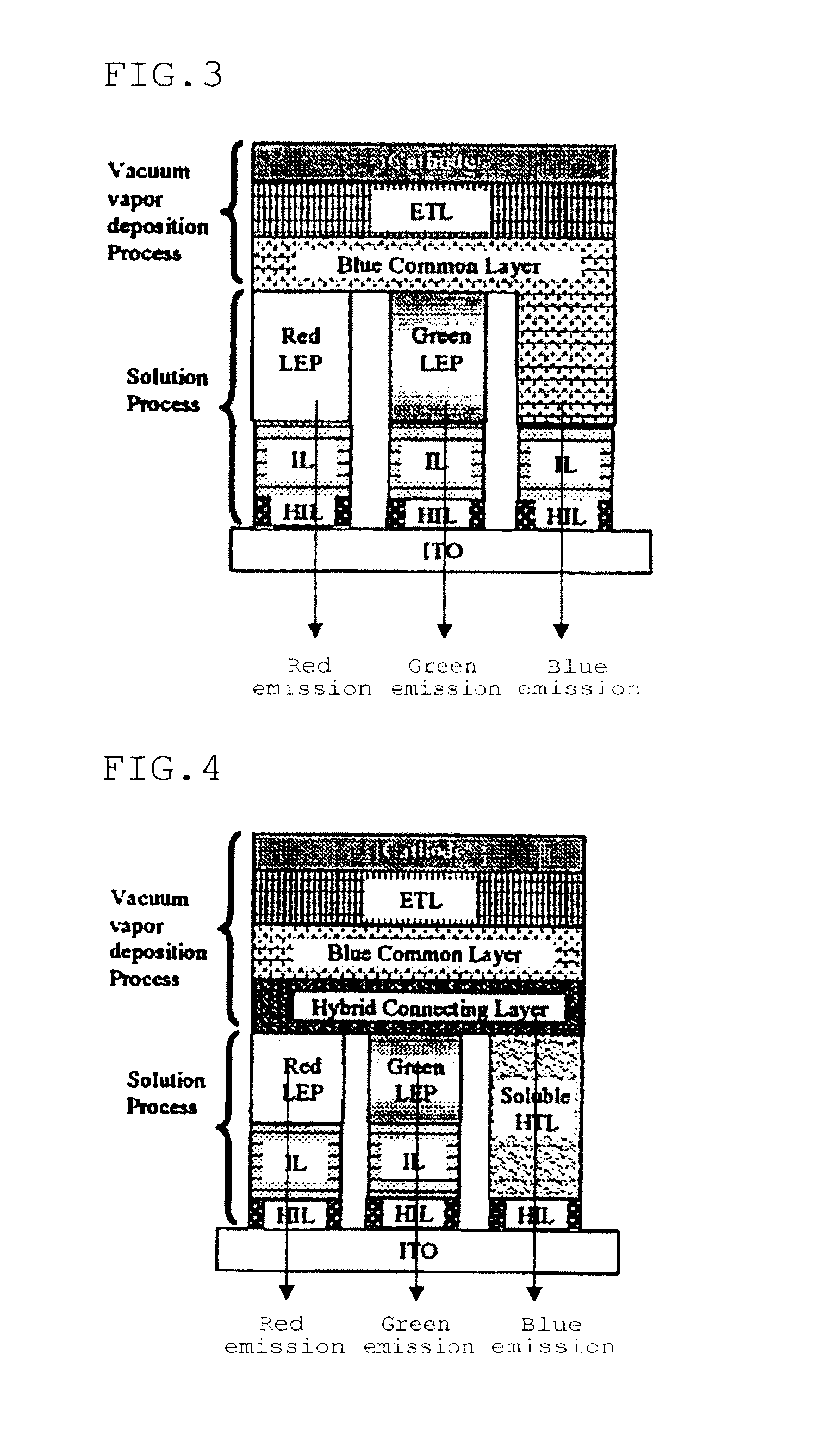
[0237]A first light-emitting element and a second light-emitting element were produced and evaluated in the same manner as in Example 1, except that the adjacent layers obtained by depositing the compounds 8 to 12 and 14 to 18 shown in Table 2 in a single layer was used instead of the first adjacent layer and the second adjacent layer formed of the compound 1. The results are shown in Table 2.
example 12
[0238]The first light-emitting element and the second light-emitting element were produced and evaluated in the same manner as in Example 1, except that the adjacent layers obtained by depositing the compound 2 in a thickness of 5 nm and subsequently the compound 1 in a thickness of 5 nm were used instead of the first adjacent layer and the second adjacent layer formed of the compound 1. The results are shown in Table 2.
PUM
| Property | Measurement | Unit |
|---|---|---|
| triplet energy | aaaaa | aaaaa |
| triplet energy | aaaaa | aaaaa |
| triplet energy | aaaaa | aaaaa |
Abstract
Description
Claims
Application Information