Wideband compact dipole manpack antenna

a dipole antenna and compact technology, applied in the direction of antennas, antenna feed intermediates, electrical devices, etc., can solve the problems of poor efficiency, general limitation of the range communication ability, and the convenience of portable radio communication devices, and achieve the effect of reducing the voltage standing wave ratio (vswr) and increasing the effective length of the assembly

Inactive Publication Date: 2014-06-12
AMI RES & DEV
View PDF2 Cites 18 Cited by
  • Summary
  • Abstract
  • Description
  • Claims
  • Application Information

AI Technical Summary

Benefits of technology

[0009]The antenna should also be designed to fit a package that is intended to be easily carried by a single person, and therefore should also be as compact as possible, while still providing good performance for long range communications.
[0010]The wideband compact antenna design described here utilizes a unique approach to connecting different radiating sections and impedance matching at the lower frequencies which is transparent to operation at higher frequencies. The dipole configuration provides isolation between the wearer and the antenna which is not available for monopole configurations, eliminating the need for bulky ground plane structures.
[0012]A bottom leg of the L-band section operates as part of the VHF / UHF section due to coupling between that lower L-band leg and the VHF / UHF section. This coupling effect reduces the required overall physical length of the antenna.
[0016]A matching network, such as an resistor-inductor-capacitor (RLC) network, can be used to lower the voltage standing wave ratio (VSWR) without affecting performance at higher frequencies.
[0017]The L-band section does not require a matching network at frequencies below 800 MHz since coupling to the VHF / UHF section(s) increases the effective length of the assembly.
[0019]The L-band section may include one or more pairs of additional cylindrical elements to improve performance; however this is at the expense of an additional 5 inches or more of length.

Problems solved by technology

Such radios have included so-called manpack radios which are bulky and typically include a relatively large antenna.
These portable radio communication devices are convenient, but generally limited in longer range communication ability.
This limitation is due in part to the poor efficiency associated with the type of antenna which is typically coupled thereto.

Method used


Image

  • Wideband compact dipole manpack antenna
  • Wideband compact dipole manpack antenna
  • Wideband compact dipole manpack antenna

Examples


Embodiment Construction

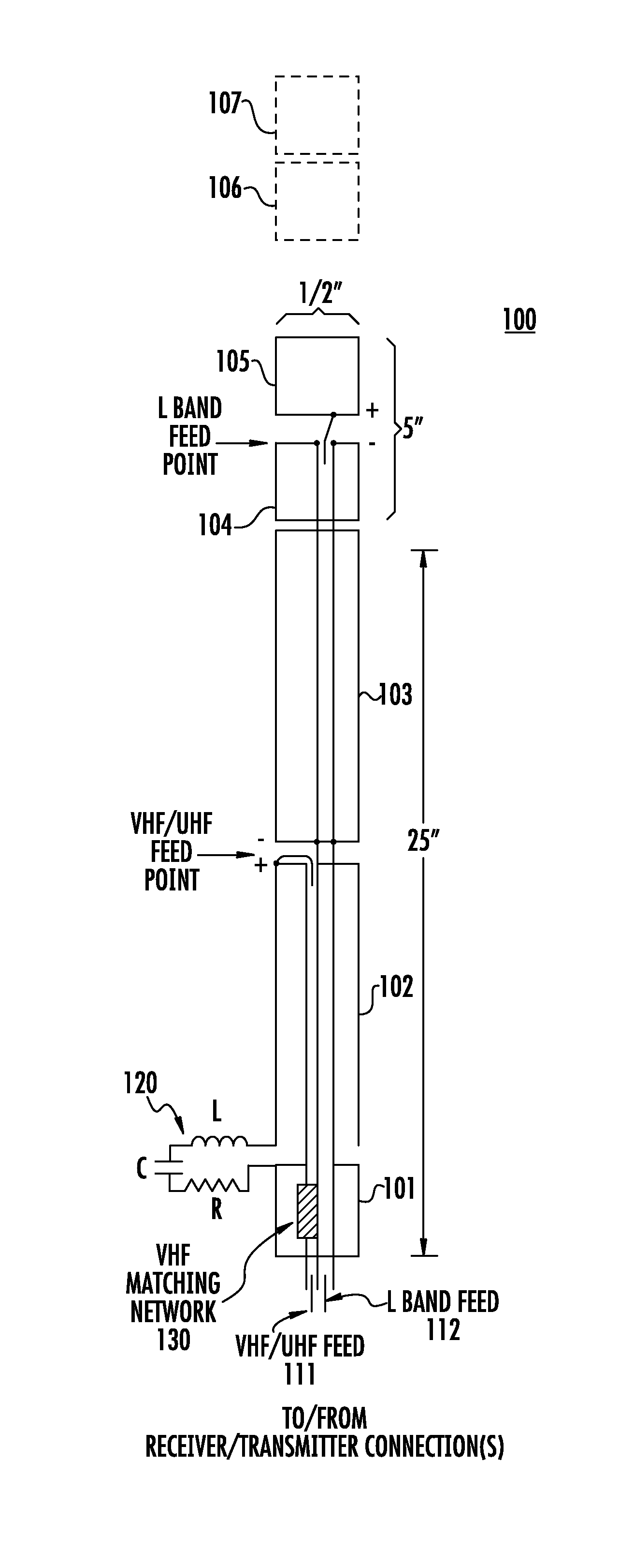
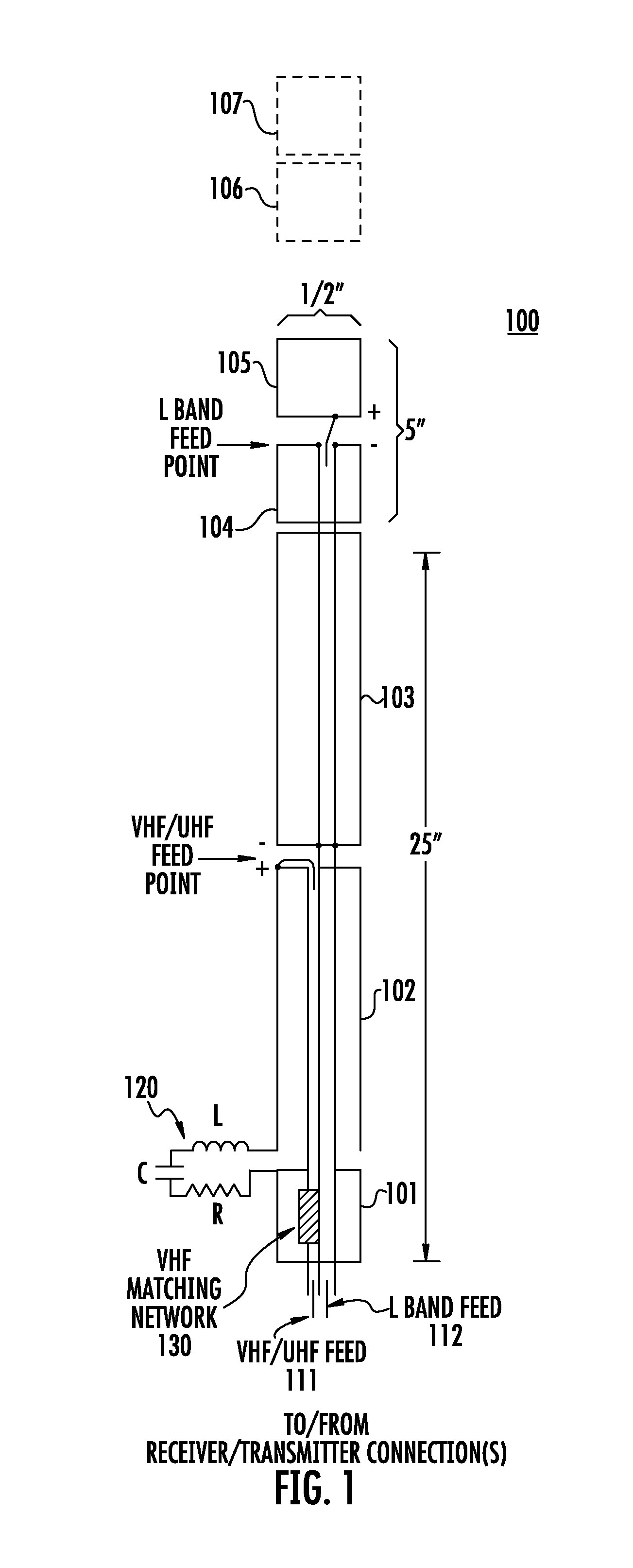
[0024]One design for a compact manpack antenna 100 operating from 100 MHz to 2000 MHz is shown in cross-section in FIG. 1. The antenna 100 is formed as an assembly of five cylindrical sections 101, 102, 103, 104, 105 coaxially arranged along a common axis. As the antenna 100 structure will typically be used in the vertical orientation with respect to the earth when operating, we will refer to the “lowest” section 101 being “below” section 102, and “upper” section 104 being “above” section 103, and so forth.

[0025]The cylindrical sections 101, 102, 103, 104, and 105 may be formed of metal or may be a dielectric having a conductive outer surface. As will be understood shortly, at least the lowest section 101 is hollowed out or has other accommodation for placing circuits within the cylinder.

[0026]The cylinders may be approximately ½ inch in diameter. The overall length of lower sections 101, 102, and 103 when taken together may be approximately 25 inches. The overall length of the two ...


PUM


Abstract

An compact manpack format antenna operating over a broad bandwidth. In one arrangement, the antenna is formed from a set of five hollow cylindrical conductive elements. Several cylinders provide, for example, a VHF / UHF radiator section and other cylinders form an L-band radiator section. A bottom leg of the L-band section operates as part of the VHF / UHF section via coupling between that lower L-band leg and the VHF / UHF section. This coupling arrangement reduces the required overall physical length of the antenna.

Description

CROSS REFERENCE TO RELATED APPLICATIONS[0001]This application claims the filing date benefit of and priority to a co-pending U.S. Provisional Patent Application Ser. No. 61 / 682,855 filed Aug. 14, 2012 and entitled “Wideband Compact Dipole Manpack Antenna”, the entire contents of which are hereby incorporated by reference.BACKGROUND[0002]1. Technical Field[0003]This disclosure relates to a wideband, compact dipole antenna for manpack applications.[0004]2. Background Information[0005]The ability to reliably communicate using wireless devices is important in many situations. Persons in almost all walks of life now commonly use mobile telephones and smartphone, for almost constant voice and data communications using different types of radio networks.[0006]But other types of portable communication devices such as portable radios continue to be used for communication between personnel such as policemen, firemen, security guards, and soldiers. Such radios have included so-called manpack ra...

Claims


Application Information

Patent Timeline
Patent Type & Authority Applications(United States)
IPC IPC(8): H01Q5/00H01Q9/28H01Q5/15
CPCH01Q9/22H01Q5/15H01Q9/28
Inventor APOSTOLOS, JOHN T.MOLEN, BRIANMCMAHON, BENJAMINMOUYOS, WILLIAM
Owner AMI RES & DEV
Why Eureka
Try Eureka