Concentric Shells for Compressed Gas Storage

a gas storage and concentrate shell technology, applied in the direction of transportation and packaging, vessel construction details, mechanical equipment, etc., can solve the problems of heavy weight of metal vessels, limited durability, weak corrosion resistance of materials, etc., and achieves low weight, high strength, and corrosion resistance.

Active Publication Date: 2014-06-19
QUANTUM FUEL SYSTEMS LLC
View PDF23 Cites 11 Cited by
  • Summary
  • Abstract
  • Description
  • Claims
  • Application Information

AI Technical Summary

Benefits of technology

[0016]In order to accomplish the objectives of the present invention, the present invention provides a method of construction for gas containment vessels that are comprised of an inner corrosion resistant shell made of lower strength steel alloy or aluminum alloy or thermoplastic polymer, and an outer concentric shell constructed of high strength, albeit lower corrosion resistant, metal or fiber-reinforced composite. The fiber can comprise filaments derived from basaltic rocks, the filaments having been immersed in a thermosetting or thermoplastic polymer matrix, and comingled with carbon, glass or aramid fibers such that there is load sharing between the basaltic fibers and carbon, glass or aramid fibers.

Problems solved by technology

However, the heavy weight of metal vessels is a serious disadvantage in automotive on-board fuel storage applications as weight impacts vehicle fuel efficiency, payload or passenger capacity and operational characteristics.
However, carbon and aramid fiber composites are very expensive compared to metals.
While glass fiber is less expensive compared to carbon fiber, this material suffers from weak corrosion resistance and limited durability under high stress conditions.
High pressure on-board fuel storage vessels—either natural gas or hydrogen cylinders—are currently required to be designed for 15-year service life, comprising up to 15,000 pressurization-depressurization cycles, while also subjected to internal and external corrosive elements, temperature extremes and mechanical damage from abrasions and impact.
Such requirements restrict material choices to a limited range of metal alloys such as 4130 steel and 6061 aluminum alloys and advanced fiber-reinforced composites.

Method used


Image

  • Concentric Shells for Compressed Gas Storage
  • Concentric Shells for Compressed Gas Storage
  • Concentric Shells for Compressed Gas Storage

Examples


Embodiment Construction

[0019]The following detailed description is of the best presently contemplated modes of carrying out the invention. This description is not to be taken in a limiting sense, but is made merely for the purpose of illustrating general principles of embodiments of the invention. The scope of the invention is best defined by the appended claims.

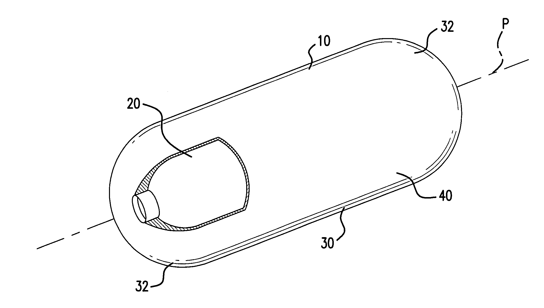
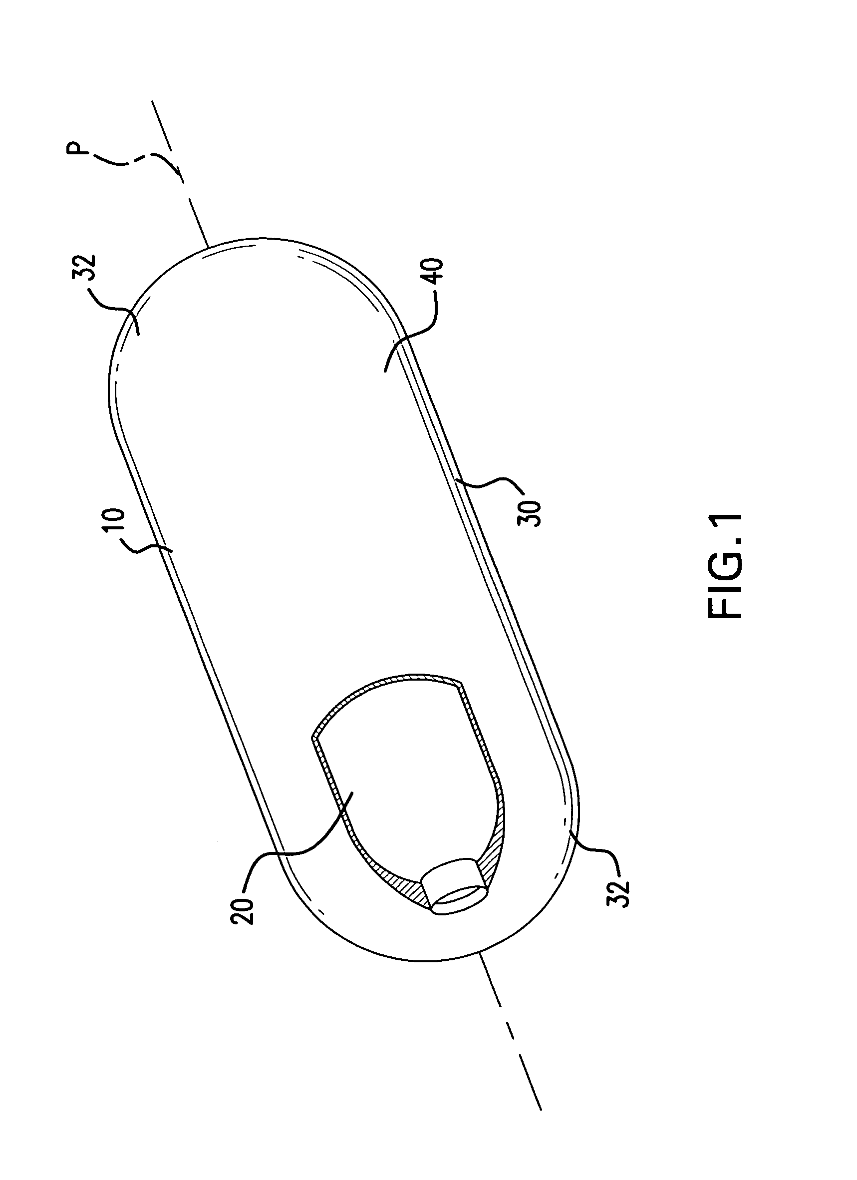
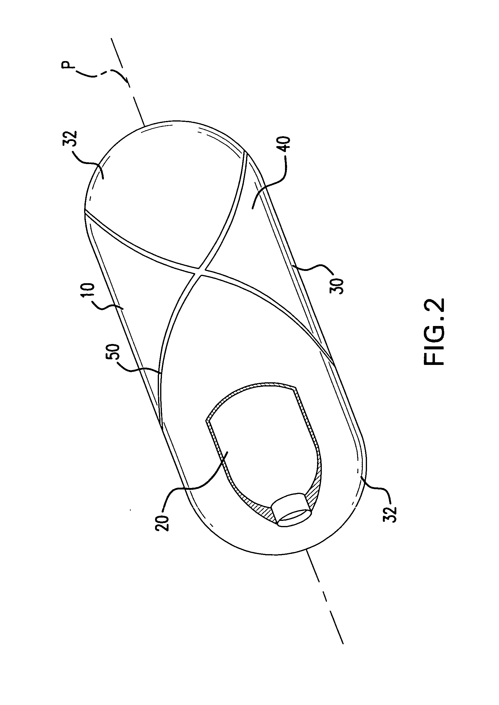
[0020]Referring to FIG. 1, the present invention provides a gas containment vessel 10 having two concentric shells and at least one polar opening. The gas containment vessel 10 includes an inner shell 20 that is configured to enclose a gas or liquid, and an outer shell 40 that provides additional structural support to contain the radial and axial loading from gas pressure. The gas containment vessel 10 may have one of a variety of shapes, including cylindrical, spherical, or combinations thereof. The pressure vessel 10 may be axially symmetric about a principal axis P extending along a longitudinal length of the vessel 10. The vessel 10 may includ...


PUM

PropertyMeasurementUnit
tensile strengthaaaaaaaaaa
diameteraaaaaaaaaa

Abstract

Gas containment vessels are provided that are comprised of an inner corrosion resistant shell made of lower strength steel alloy or aluminum alloy or thermoplastic polymer, and an outer concentric shell constructed of high strength, albeit lower corrosion resistant, metal or fiber-reinforced composite. The fiber can comprise filaments derived from basaltic rocks, the filaments having been immersed in a thermosetting or thermoplastic polymer matrix, and comingled with carbon, glass or aramid fibers such that there is load sharing between the basaltic fibers and carbon, glass or aramid fibers.

Description

BACKGROUND OF THE INVENTION[0001]1. Field of the Invention[0002]The present invention relates to high pressure gas containment devices, and in particular, natural gas and hydrogen gas storage vessels composed of concentric shells having reduced weight and at reduced cost.[0003]2. Description of the Prior Art[0004]The use of alternative fuels such as natural gas and hydrogen is expanding rapidly worldwide, as the growing automotive industry is seeking sustainable, ecologically cleaner, and less expensive fuels.[0005]Natural gas and hydrogen fuel are commonly stored in pressure vessels on-board vehicles, highly compressed to improve the gravimetric energy density and volumetric storage efficiency of these gaseous fuels. Compressed gas vessels must be strong and resistant to cyclic loading, corrosive chemicals, temperature extremes, abrasion and impact loads, as well as resistant to the corrosive constituents of natural gas or hydrogen fuel.[0006]At present, on-board fuel storage vesse...

Claims


Application Information

Patent Timeline
Patent Type & Authority Applications(United States)
IPC IPC(8): F17C1/10
CPCF17C2201/0104F17C2201/0109F17C2201/0128F17C2201/056F17C2201/06F17C2203/0604F17C2203/0619F17C2203/0646F17C2203/0648F17C2203/0656F17C2203/066F17C2203/0663F17C2203/0675F17C2209/2154F17C2209/2181F17C2209/234F17C2221/012F17C2221/033F17C2223/0123F17C2223/036F17C2270/0178F17C1/02Y02E60/32F17C1/06F17C2203/0639
Inventor SIROSH, NEEL
Owner QUANTUM FUEL SYSTEMS LLC
Why Eureka
Try Eureka