Liquid crystal display

a liquid crystal display and display device technology, applied in non-linear optics, instruments, optics, etc., can solve the problems of complex pitaxy process, inability to have identical photoelectric properties of light-emitting diodes manufactured on the same wafer, and achieve the effect of reducing the fabrication cost of liquid crystal displays, reducing the yield of bins, and increasing the utilization rate of light-emitting diodes

Inactive Publication Date: 2014-06-19
RADIANT OPTO ELECTRONICS
View PDF6 Cites 18 Cited by
  • Summary
  • Abstract
  • Description
  • Claims
  • Application Information

AI Technical Summary

Benefits of technology

[0014]Therefore, one aspect of the present invention is to provide a liquid crystal display, which uses blue light-emitting diodes as light sources. Accordingly, a bin yield loss during packaging caused by using white light-emitting diodes is eliminated, and a utilization rate of the light-emitting diodes is increased, thereby reducing a fabrication cost of the liquid crystal display.

Problems solved by technology

The epitaxy process is complicated, so that the light-emitting diode chips 108 manufactured on the same wafer cannot have identical photoelectric property.
Therefore, after the white light light-emitting diodes 120 are completed, a part of the white light light-emitting diodes 120, which do not conform to the color requirement, are abandoned by manufacturers through a bin-sorting procedure, thereby increasing the fabrication cost.
Therefore, the utilization efficiency of the light emitted by the light-emitting diodes 120 is poor.

Method used


Image

  • Liquid crystal display
  • Liquid crystal display
  • Liquid crystal display

Examples


Embodiment Construction

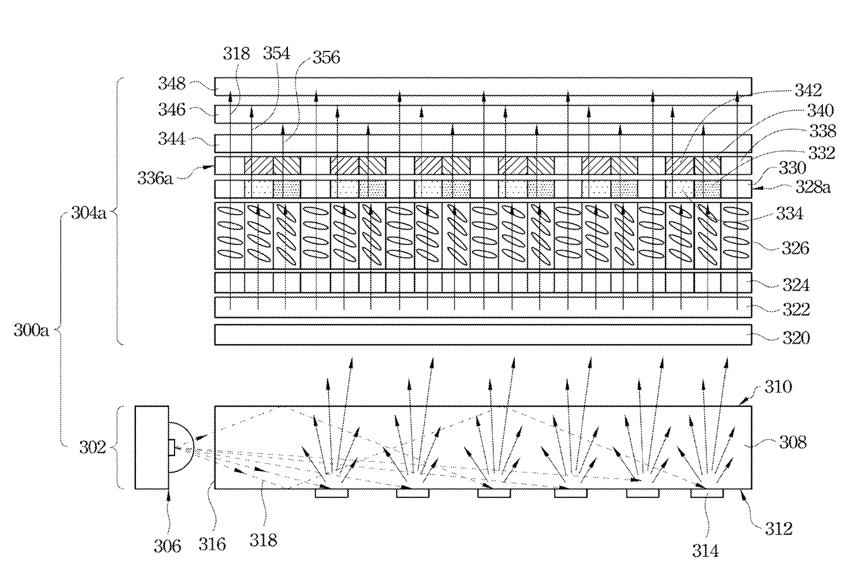
[0038]In viewing of the aforementioned conditions, the present application provides a liquid crystal display design to prevent the aforementioned disadvantages of the conventional liquid crystal display. Refer to FIG. 3. FIG. 3 is a schematic diagram showing a liquid crystal display in accordance with an embodiment of the present invention. In the present embodiment, a liquid crystal display 300a mainly includes a backlight module 302 and a liquid crystal display panel 304a. The backlight module 302 mainly includes a plurality of blue light-emitting diodes 306 and a light guide plate 308. The light guide plate 308 is a transparent plate body, which can transmit light. The light guide plate 308 includes a light-entering surface 316, a light-emitting surface 310 and a reflective surface 312. The light-emitting surface 310 and the reflective surface 312 are opposite to each other, and the light-entering surface 316 is connected to one edge of the light-emitting surface 310 and one edge...


PUM

PropertyMeasurementUnit
transmittanceaaaaaaaaaa
transparentaaaaaaaaaa
photoelectric propertyaaaaaaaaaa

Abstract

A liquid crystal display is described, which includes a backlight module and a liquid crystal display panel. The backlight module includes a light guide plate and a plurality of blue light-emitting diodes adjacent to the light guide plate. The liquid crystal display panel is disposed above the backlight module. The liquid crystal display panel includes a first transparent substrate, a first electrode, a liquid crystal layer, a phosphor powder layer, a color filter, a second electrode and a second transparent substrate stacked above the light guide plate in sequence. The phosphor powder layer includes a plurality of green phosphor powder regions and red phosphor powder regions. The color filter is adjacent to the phosphor powder layer. The color filter includes a plurality of green color filter regions and red color filter regions respectively and correspondingly located, on the green phosphor powder regions and the red phosphor powder regions.

Description

RELATED APPLICATIONS[0001]This application claims priority to Taiwan Application Serial Number 101148365, filed Dec. 19, 2012, which are herein incorporated by reference.FIELD OF THE INVENTION[0002]The present invention relates to a flat panel display device, and more particularly to a liquid crystal display (LCD).BACKGROUND OF THE INVENTION[0003]Refer to FIG. 1. FIG. 1 is a schematic diagram showing a conventional liquid crystal display. A liquid crystal display 100 mainly includes a backlight module 102 and a liquid crystal display panel 104. The backlight module 102 is disposed on a rear side of the liquid crystal display panel 104 to provide the liquid crystal display panel 104 with light. The backlight module 102 typically includes a light guide plate 106 and a plurality of light-emitting diodes (LEDs) 120. The light-emitting diodes 120 are disposed beside a side surface of the light guide plate 106. Each light-emitting diode 120 includes a light-emitting diode chip 108 and a p...

Claims


Application Information

Patent Timeline
Patent Type & Authority Applications(United States)
IPC IPC(8): G02F1/1335
CPCG02F1/133603G02F1/133514G02F1/133617
Inventor WU, YI-TSUO
Owner RADIANT OPTO ELECTRONICS
Why Eureka
Try Eureka