Low inductance and low resistance hermetically sealed filtered feedthrough for an aimd
- Summary
- Abstract
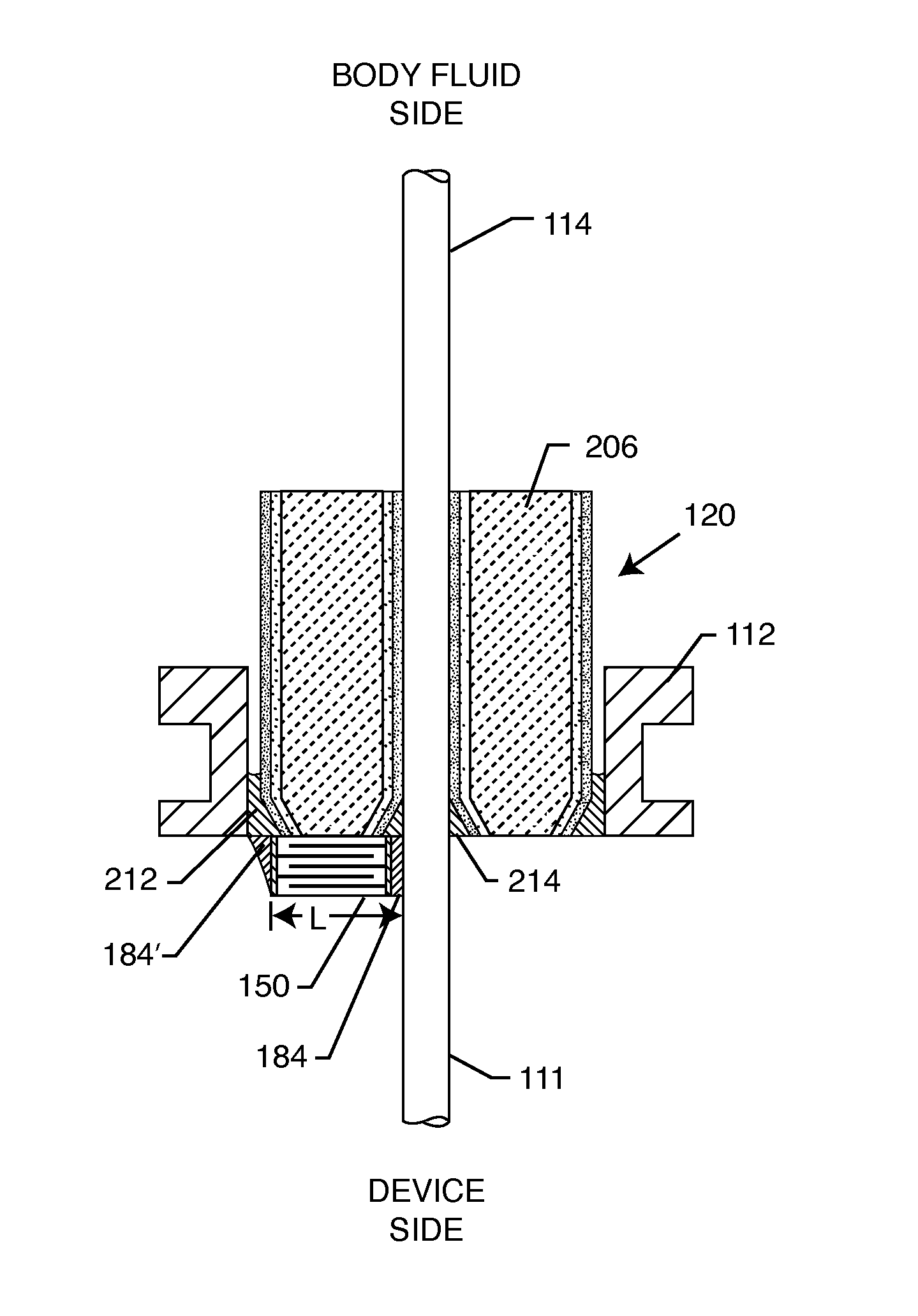
- Description
- Claims
- Application Information
AI Technical Summary
Benefits of technology
Problems solved by technology
Method used
Image

Examples
Embodiment Construction
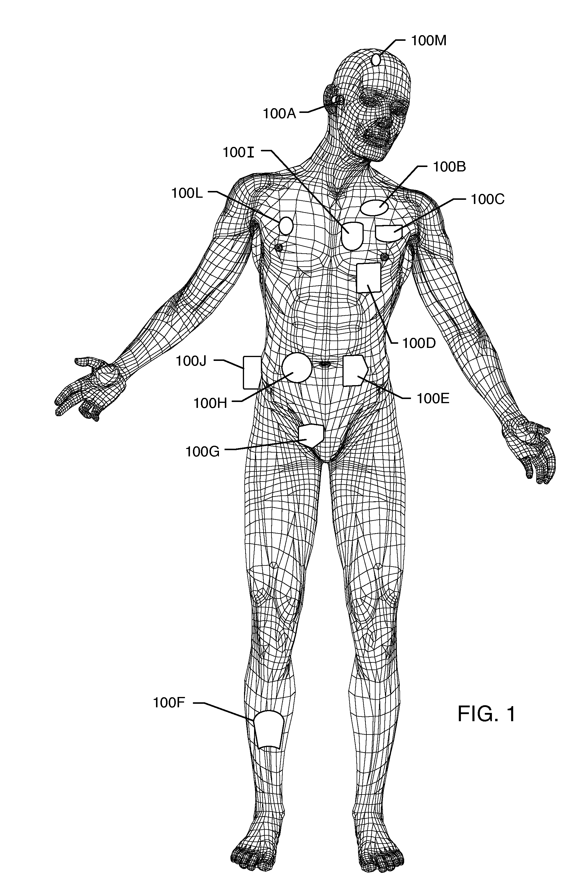
[0104]FIG. 1 is a wire-formed diagram of a generic human body showing various types of active implantable and external medical devices 100 that are currently in use. 100A is a family of external and implantable hearing devices which can include the group of hearing aids, cochlear implants, piezoelectric sound bridge transducers and the like. 100B includes an entire variety of neurostimulators and brain stimulators. Neurostimulators are used to stimulate the Vagus nerve, for example, to treat epilepsy, obesity and depression. Brain stimulators are similar to a pacemaker-like device and include electrodes implanted deep into the brain for example but not limited to sensing the onset of the seizure and also providing electrical stimulation to brain tissue to prevent the seizure from actually happening, or for treating memory loss, Alzheimer's and the like. The lead wires that come from a deep brain stimulator are often placed using real time imaging. Most commonly such lead wires are p...
PUM
 Abstract
Description
Claims
Application Information