Lithium secondary battery negative electrode and method for manufacturing the same

a secondary battery and negative electrode technology, applied in the direction of cell components, final product manufacturing, sustainable manufacturing/processing, etc., can solve the problems of high-speed charging/discharging, carbon nanowalls, and the upper limit of 372 mah, and achieve the effect of small battery capacity reduction and large charging/discharging capacity

Active Publication Date: 2014-06-19
SANGO CO LTD +1
View PDF9 Cites 23 Cited by
  • Summary
  • Abstract
  • Description
  • Claims
  • Application Information

AI Technical Summary

Benefits of technology

[0044]According to the present invention, there is provided a lithium secondary battery negative electrode in which a theoretical electric capacity is much larger than the theoretical electric capacity when an

Problems solved by technology

While graphite has been used as the negative active material for lithium secondary batteries, it is not suitable for high-speed charging/discharging due to its large crystallite size (micron order).
Carbon nanowalls are, however, disadvantageous in that the number of lithium atoms to be intercalated between layers is 1 in every 6 carbon atoms and the charging/discharging capacities theoretically have an upper limit of 372 mAh/g.
Therefore, when silicon is used as the negative active material

Method used


Image

  • Lithium secondary battery negative electrode and method for manufacturing the same
  • Lithium secondary battery negative electrode and method for manufacturing the same
  • Lithium secondary battery negative electrode and method for manufacturing the same

Examples


embodiment 1

1. (Embodiment 1)

[0091]A disc with a side of 016 mm is punched in a 1 mm-thick stainless steel (austenitic stainless steel SUS304) sheet and the sheet is used as a negative current collector substrate.

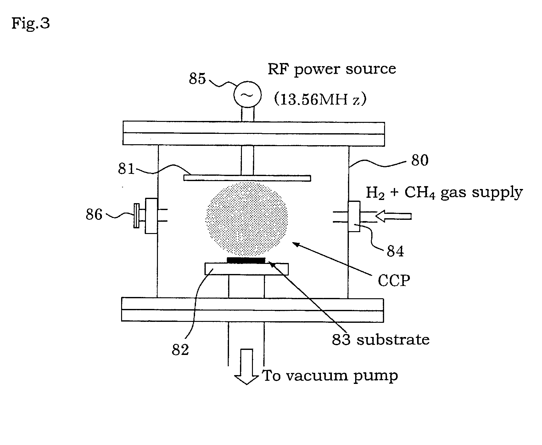
[0092]Subsequently, the stainless steel sheet in which the disc has been punched is placed in a chamber of a plasma CVD system (see FIG. 3) and plasma CVD is performed in the following conditions. For comparison, plasma CVD is performed as well under the condition that the temperature of the current collector substrate is 600° C.

Flow gas: a gaseous mixture of hydrogen (20% by volume) and methane (80% by volume)

Flow rate of gaseous mixture: 60 sccm

Temperature of current collector substrate: 750° C.

Process pressure: 0.1 Torr (13.3 Pa)

Time: 1 hour

DC bias voltage: 0 V

Applied high-frequency output: 100 W

Applied high frequency: 13.56 MHz

Distance from the electrode to the current collector substrate: 25 mm

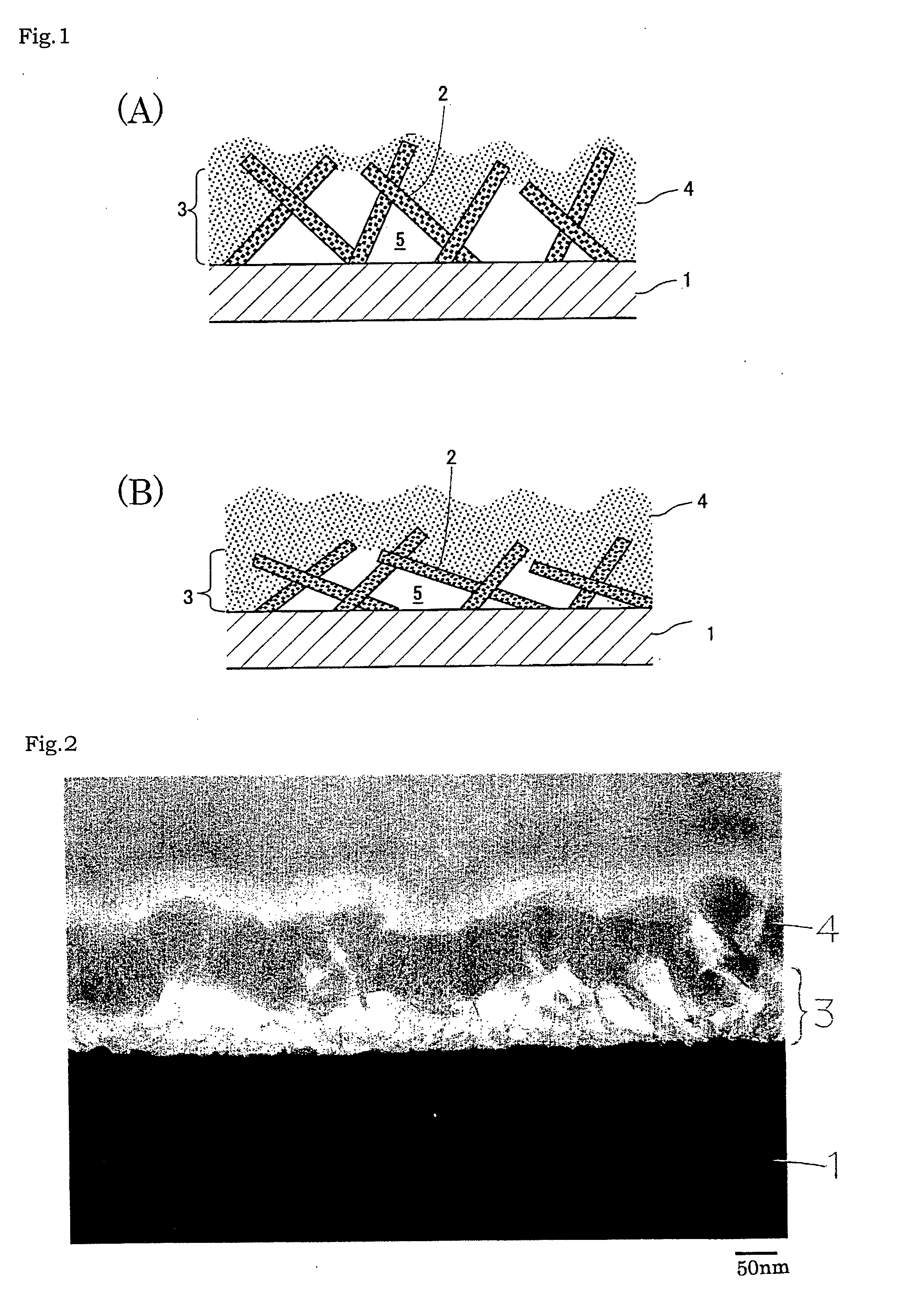
[0093]A chart of a Raman spectrum of the thus obtained sample and a scanning electron mi...

embodiment 2

[0103]In Embodiment 2, an oxygen cleaning step is performed in which the respective surfaces of the current collector substrate and the plasma CVD electrode are cleaned with oxygen under the following conditions, prior to the step of forming the carbon nanochips layer by a plasma CVD method in Embodiment 1. The other steps in Embodiment 2 are similar to the steps in Embodiment 1 in which the carbon nanochips layer is formed by a plasma CVD method under the condition that the temperature of the substrate is 750° C., and the descriptions thereof will be omitted.

Flow gas: oxygen 100%

Flow rate of gas: 60 sccm

Temperature of current collector substrate: 80° C. at lowest, 180° C. at highest

Process pressure: 0.8 Torr (100 Pa)

Time: 1 hour

Applied high-frequency output: 100 W

Applied high frequency: 13.56 MHz


PUM

PropertyMeasurementUnit
Temperatureaaaaaaaaaa
Timeaaaaaaaaaa

Abstract

Provided is a negative electrode having a new structure for realizing a lithium secondary battery having increased charging/discharging capacities and a battery capacity that is reduced less due to repeated charging/discharging. The negative electrode for a lithium secondary battery includes a current collector substrate; a carbon nanochips layer including graphene sheets grown to incline in irregular directions independently from the current collector substrate; and a silicon thin film layer on the carbon nanochips layer, in which gaps among the carbon nanochips are formed between the silicon thin film layer and the current collector substrate. The Raman spectrum of graphite forming the carbon nanochips layer has a g/d ratio of 0.30 to 0.80, both inclusive, and the crystallinity level of the graphite is lower than that of graphite forming carbon nanowalls. The carbon nanochips layer can be formed by a plasma CVD method using a gaseous mixture of methane and hydrogen, for example.

Description

TECHNICAL FIELD[0001]The present invention relates to negative electrodes for lithium secondary batteries and a method for manufacturing the negative electrodes for lithium secondary batteries.BACKGROUND ART[0002]In recent years, mobile electronic devices such as mobile phones and notebook-sized personal computers have played an important role in the information society. The electronic devices need to be in a driving state over a long period of time, and high energy densities have been therefore required for secondary batteries used as driving power sources of the electronic devices.[0003]In order to supply powers to the electronic devices and transporting systems such as vehicles, there is a need for high-performance lithium secondary batteries with reduced weights and increased energy densities. A lithium secondary battery has a configuration in which an electrolyte solution or a lithium solid electrolyte is sandwiched between a negative active material and a positive active mater...

Claims


Application Information

Patent Timeline
IPC IPC(8): H01M4/583H01M4/04H01M4/1395C23C16/26C23C16/513
CPCH01M4/583C23C16/26H01M4/1395H01M4/0428C23C16/513C23C16/5096H01M4/134H01M4/362H01M4/386H01M4/625H01M4/661Y02E60/10H01M4/133H01M4/1393Y02P70/50
Inventor IZUHARA, KOUICHIDAIFUKU, MAKOTOMIYATA, YASUSHI
Owner SANGO CO LTD
Why Eureka
Try Eureka