Hybrid photonic crystal fiber, and method for manufacturing same

a technology of photonic crystal fiber and manufacturing method, which is applied in the direction of manufacturing tools, cladding optical fiber, instruments, etc., can solve the problems of troublesome procedure, blockage of hole and air hole of cladding, and complicated method, etc., and achieve the effect of high efficiency of the manufacturing process

Inactive Publication Date: 2014-06-26
IND ACADEMIC CORP FOUND YONSEI UNIV
View PDF6 Cites 42 Cited by
  • Summary
  • Abstract
  • Description
  • Claims
  • Application Information

AI Technical Summary

Benefits of technology

[0022]The hybrid photonic crystal fiber of the present invention includes a central core, whose shape may vary, formed by filling with a functional material such as a liquid, a liquid crystal or a biofluid. In response to changes in the state of the functional material, light intensity, wavelength, phase and polarization can be modulated. Thus, the hybrid photonic crystal fiber of the present invention is suitable for use in the construction of various optical communication networks and can serve as an optical sensor capable of detecting changes in refractive index caused by external stresses such as temperature and pressure. The use of a fluorescent dye as the functional material enables the utilization of the hybrid photonic crystal fiber as a light source of a fluorescent dye laser in the visible region. The use of a high nonlinear liquid as the functional material enables the utilization of the hybrid photonic crystal fiber as a light source of an ultra-broadband laser at 700 nm or higher. The method of the present invention requires no additional process for air hole blocking or fusion splicing, making the fabrication procedure highly efficient while maintaining the size of liquid core.

Problems solved by technology

For this reason, the procedure of the method is rather complicated: a central hole portion is first blocked with UV curable polymer, the UV curable polymer is again filled in the cladding air holes and is again cured, and thereafter, only the blocked portions of the cladding are cleaved appropriately before filling the central hole with liquid.
However, it is necessary to undergo a troublesome procedure for optimizing the intensity and time of arc discharge in different optical fibers.
Further, when the central hole size is not significantly different from the size of air holes in the cladding region, there is a high possibility that the central hole and the air holes of the cladding may be blocked together, making it impossible to practically apply the method.
The speed difference between such polarization modes leads to dispersion of light, causing many problems such as bit errors in the construction of high-speed optical communication networks of 10 Gbps or higher.
However, to the best of our knowledge, no studies have been conducted on the fabrication of elliptical liquid core optical fibers, and no report has appeared on liquid core optical fibers with various core shapes and photonic crystal fibers that can be used as birefringence control devices through changes in the state of liquids in response to ambient factors such as temperature and pressure.

Method used


Image

  • Hybrid photonic crystal fiber, and method for manufacturing same
  • Hybrid photonic crystal fiber, and method for manufacturing same
  • Hybrid photonic crystal fiber, and method for manufacturing same

Examples


fabrication example 1

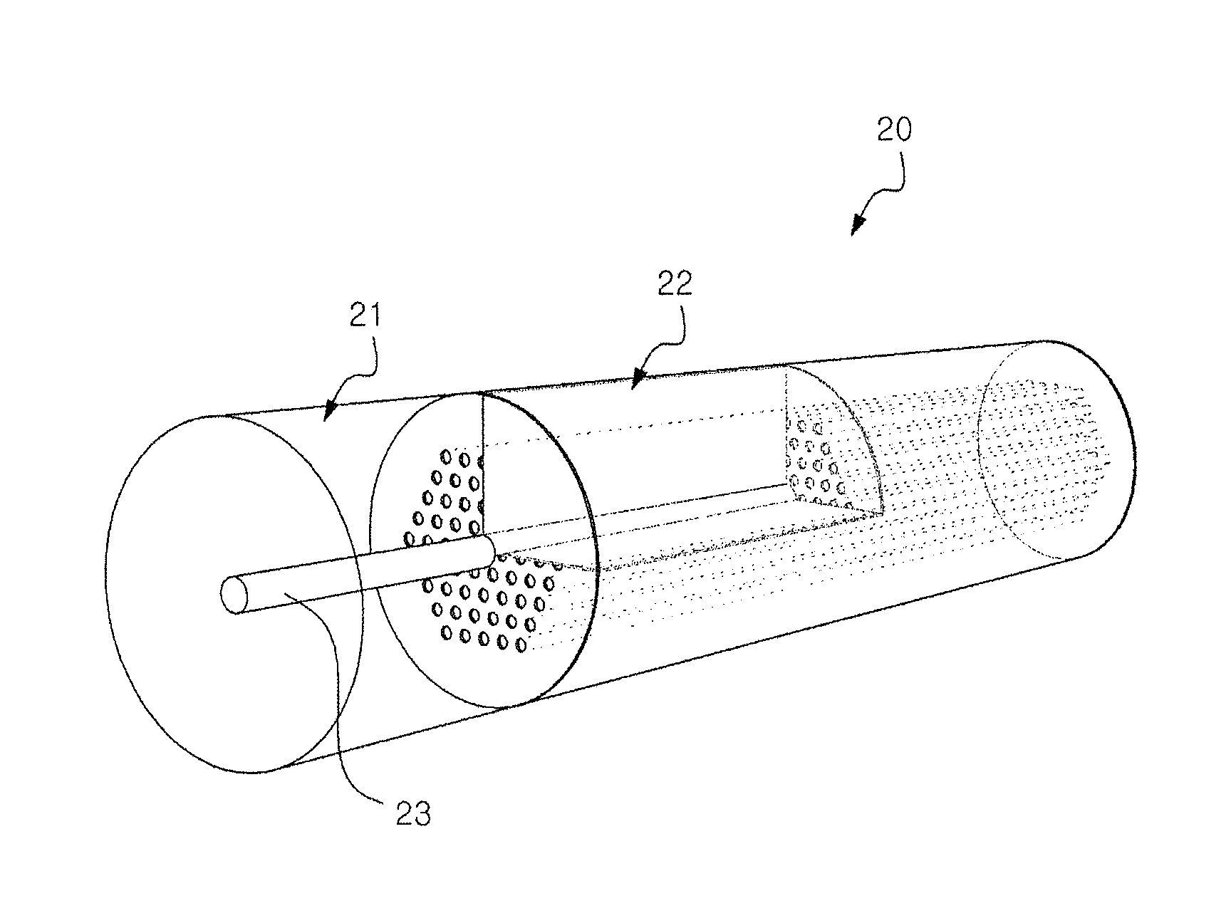
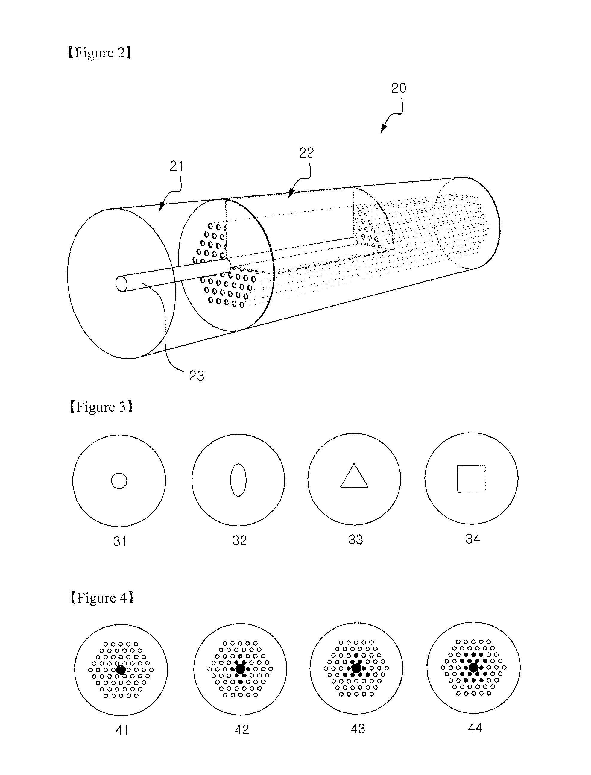
[0057](1) Splicing of the Hollow Optical Fiber and the Photonic Crystal Fiber

[0058]For the fabrication of the liquid core photonic crystal fiber, a functional liquid is filled in the central hole of the photonic crystal fiber through the hollow optical fiber. To this end, the air holes formed at both ends of the photonic crystal fiber should be maintained constant without size reduction during splicing between the photonic crystal fiber and the hollow optical fiber. When a splicing condition for general single-mode optical fibers (SMF-28) is used, air holes at both ends are completely blocked, and as a result, a liquid cannot be induced through the hollow optical fiber, making it impossible to fill the liquid.

[0059]Optimized intensities and times of arc discharge for splicing between the hollow optical fiber and the photonic crystal fiber using a fusion splicer (Ericsson FSU975) are compared with those of arc discharge for splicing single-mode optical fibers. The results are shown i...

experimental example 1

Incidence of Light on the Liquid Core Photonic Crystal Fiber

[0073]Light is launched to the liquid core photonic crystal fiber fabricated in Fabrication Example 1. Effective incidence of light from conventional light sources (e.g., white light sources and laser diodes) is analyzed numerically and verified empirically. The hollow optical fiber as a liquid delivery tube is advantageous in terms of ease of mode conversion from a general single-mode optical fiber. Due to this advantage, the hollow optical fiber can be used as a light waveguide for effective incidence of light on the liquid core photonic crystal fiber. Accordingly, there is no need to remove the hollow optical fiber after completion of the liquid filling.

[0074]For this usage, an important requirement is that a ring core doped with a high refractive index material should be present in the hollow optical fiber. Otherwise, a large amount of light is lost to the cladding because the central air hole filled with liquid has a l...


PUM

PropertyMeasurementUnit
diameteraaaaaaaaaa
diameteraaaaaaaaaa
diameteraaaaaaaaaa

Abstract

The present invention relates to a hybrid photonic crystal fiber, into the core of which a functional material is injected. The hybrid photonic crystal fiber of the present invention comprises: a central hole having a diameter of 4 to 15 μm extending in the longitudinal direction; an inner cladding also formed in the longitudinal direction outside the central hole, having a hexagonal arrangement of air holes, each of which has a diameter of 2 to 5 μm and a lattice constant of 4.5 to 7 μm; an annular outer cladding surrounding the outer surface of the inner cladding; and a core formed by filling a functional material in some of the air holes including the central hole. According to the present invention, changes in the state, i.e. the liquid, liquid-crystal, or biofluid states, of the functional material that fills the core that has a variety of shapes may enable the modulation of light intensity, wavelength, phase, and polarization, and thus enable various photonic networks to be produced. The hybrid photonic crystal fiber of the present invention may serve as various optical sensors capable of sensing changes in refractive index caused by external stresses such as temperature and pressure. The hybrid photonic crystal fiber of the present invention may be used as a light source for a fluorescent dye laser for a visible ray zone using fluorescent dye, or for an ultra-wideband laser of 700 nm or higher using high nonlinear liquid.

Description

TECHNICAL FIELD[0001]The present invention relates to a hybrid photonic crystal fiber including a core formed by filling with a functional material. More specifically, the present invention relates to a hybrid photonic crystal fiber including a central core, whose shape may vary, formed by filling with a functional material such as a liquid, a liquid crystal or a biofluid wherein light intensity, wavelength, phase and polarization can be modulated in response to changes in the state of the functional material, thus being suitable for use in the construction of various optical communication networks and the application to fluorescent dye lasers and optical sensors, and a method for fabricating a hybrid photonic crystal fiber including a core, whose shape may vary, formed by filling with a functional material without changing the size of the core.BACKGROUND ART[0002]With the recent developments of photonic crystal fibers (PCFs) in which air holes are regularly arranged in silica glass...

Claims


Application Information

Patent Timeline
Patent Type & Authority Applications(United States)
IPC IPC(8): G02B6/02C03B37/15
CPCG02B6/02328G02B6/032C03B37/15G02B6/02314
Inventor OH, KYUNG-HWANPARK, JI-YOUNG
Owner IND ACADEMIC CORP FOUND YONSEI UNIV
Why Eureka
Try Eureka