Thermoelectric conversion element and thermoelectric conversion method

a conversion element and thermoelectric technology, applied in the direction of thermoelectric devices with peltier/seeback effect, thermoelectric device manufacturing/treatment, electrical apparatus, etc., can solve the problems of non-uniform in-plane temperature distribution in buildings, non-uniform heat generation in some portions, and inability of conventional thermoelectric conversion elements based on thermocouples to convert the temperature gradient in the in-plane direction of heat source into electric power,

Inactive Publication Date: 2014-07-03
NEC CORP +1
View PDF4 Cites 5 Cited by
  • Summary
  • Abstract
  • Description
  • Claims
  • Application Information

AI Technical Summary

Benefits of technology

[0020]According to this invention, it is possible to provide the thermoelectric conversion element capable of converting both the temperature

Problems solved by technology

In practice, a non-uniform in-plane temperature distribution is generated in buildings and IT devices under various situations.
A server or the like also has non-uniform heat generation in some portions.
Therefore, the conventional thermoelectric

Method used


Image

  • Thermoelectric conversion element and thermoelectric conversion method
  • Thermoelectric conversion element and thermoelectric conversion method
  • Thermoelectric conversion element and thermoelectric conversion method

Examples


example 1

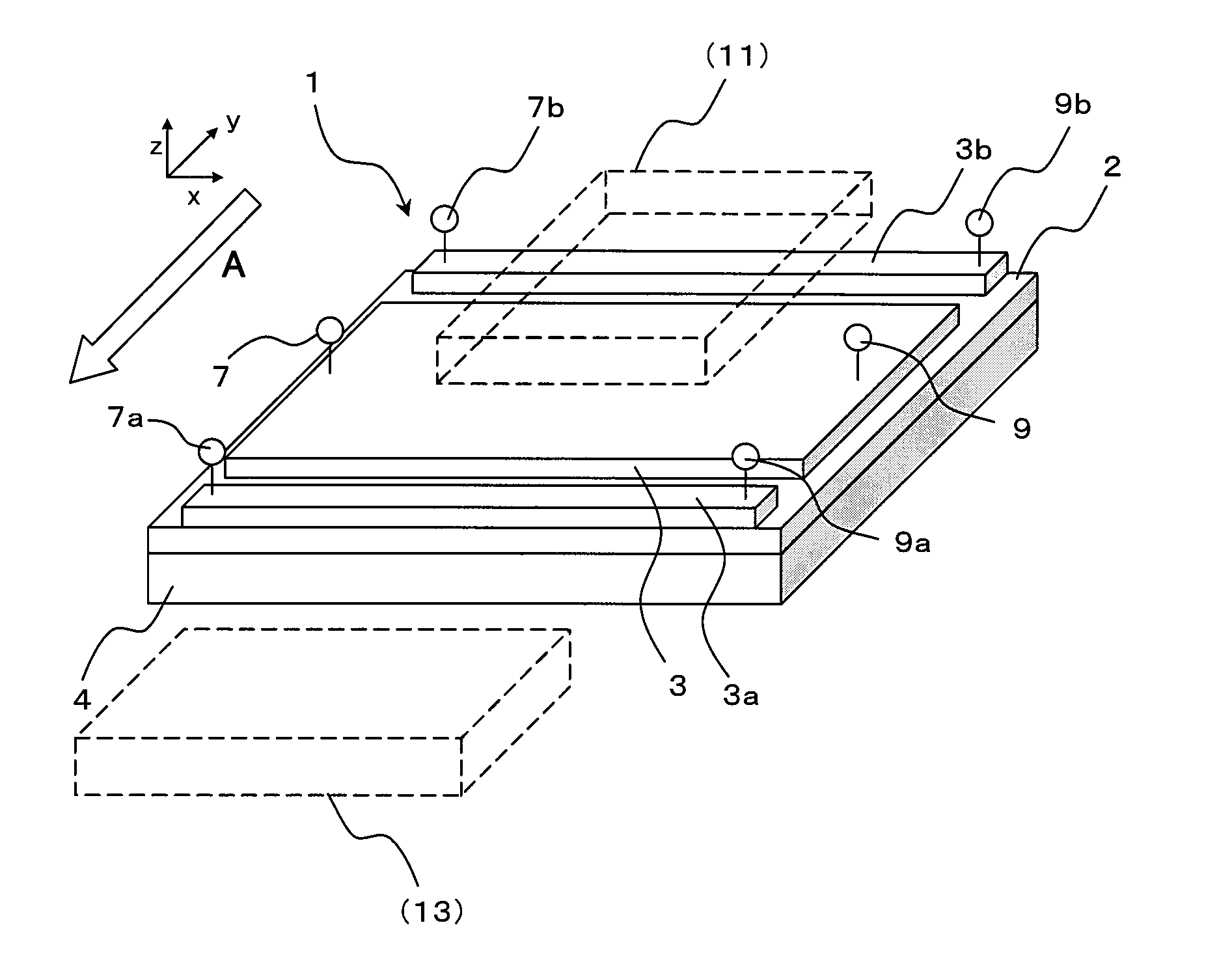
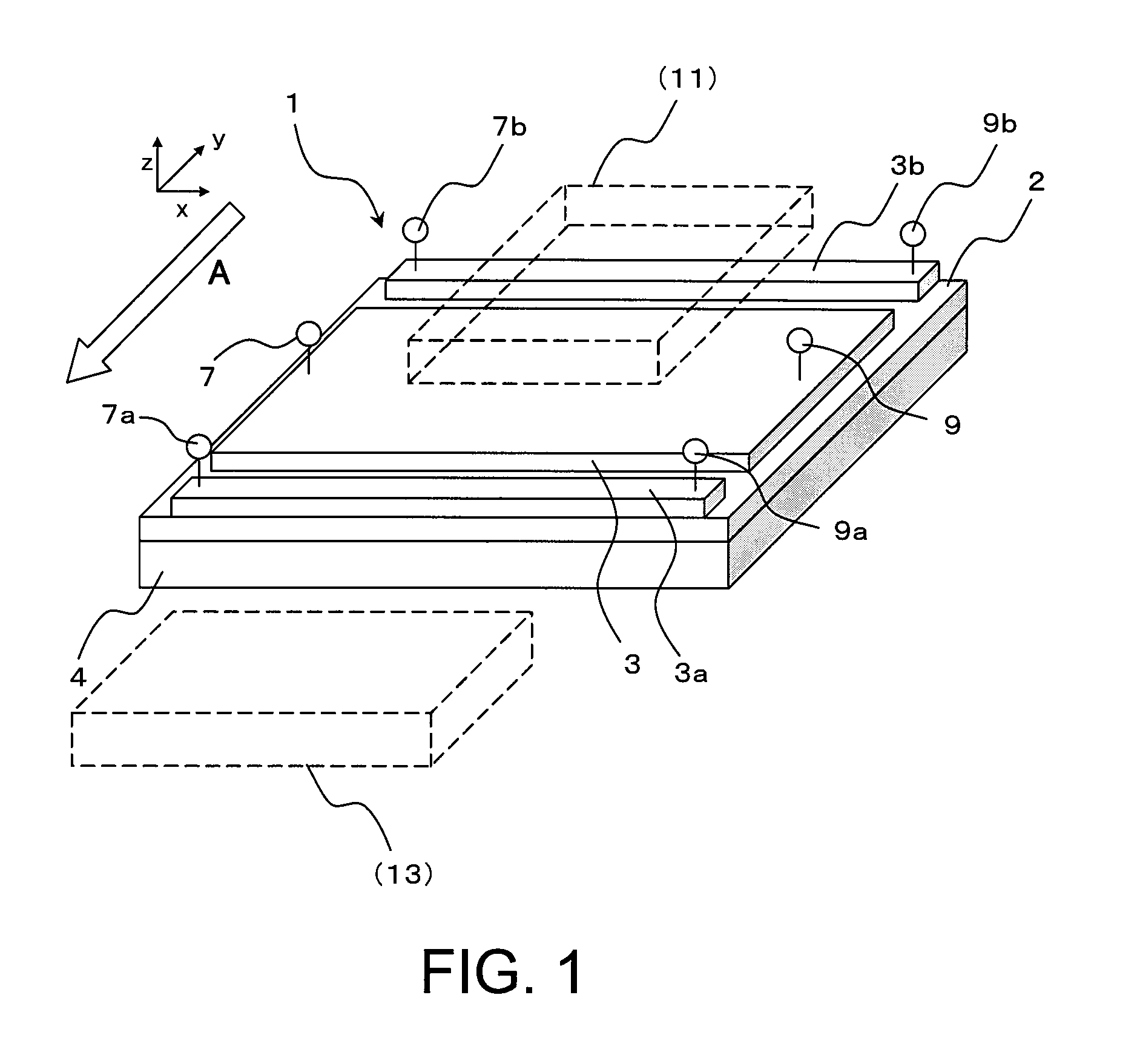
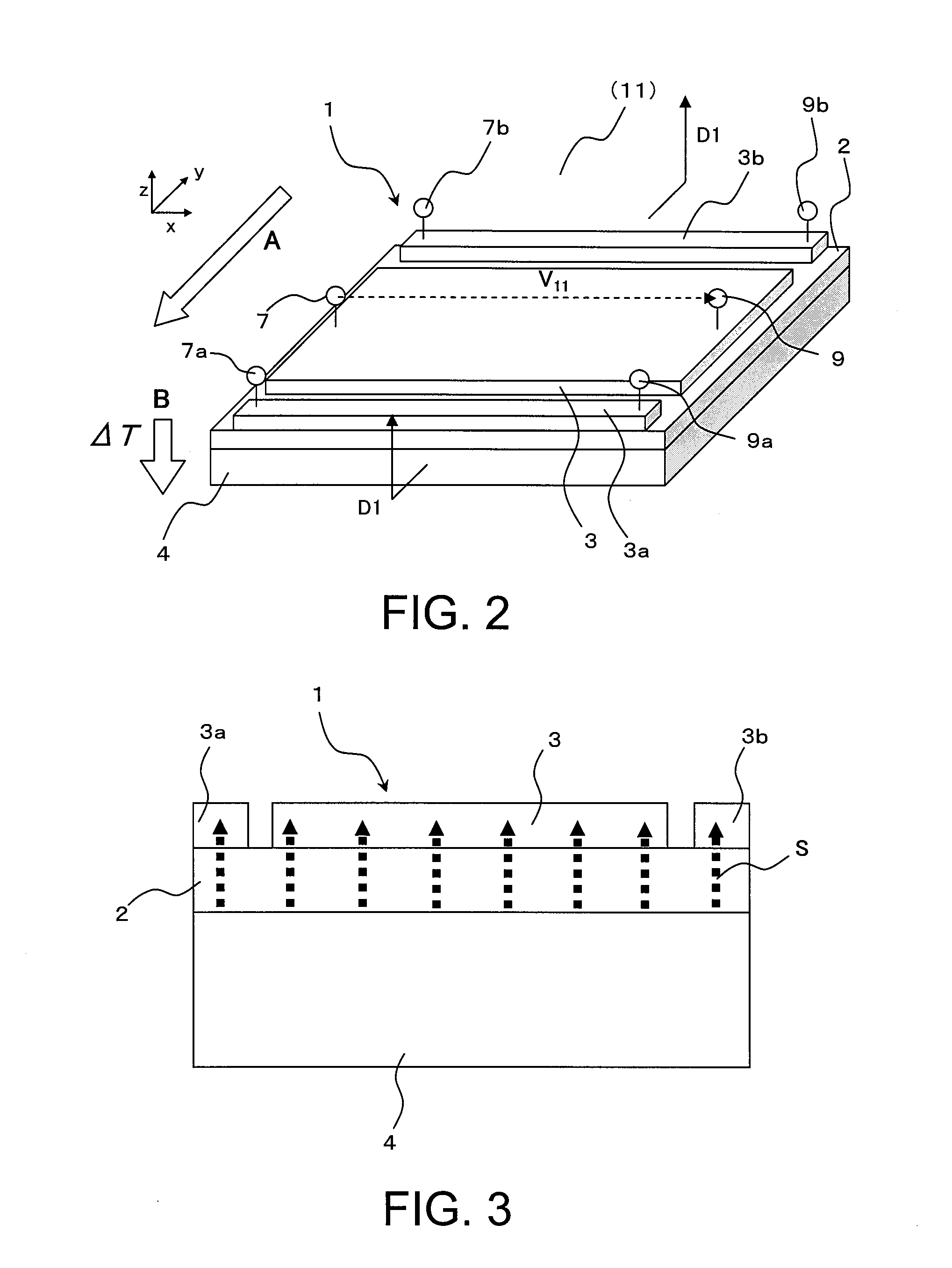
[0221]The thermoelectric conversion element 1 according to the first embodiment was manufactured. A specific procedure was as follows.

[0222]First, as the substrate 4, a (111) plane of a gadolinium gallium garnet (hereinafter referred to as “GGG”; a composition thereof was Gd3Ga5O12) substrate manufactured by Saint-Gobain K. K was used. As the magnetic film 2, an yttrium iron garnet film having a Y-site partially substituted by Bi (composition thereof was BiY2Fe5O12; hereinafter referred to as “Bi:YIG”) was used. For the electrodes 3, 3a, and 3b, Pt was used. In this case, a thickness of the GGG substrate was set to 0.7 mm, a thickness of the Bi:YIG film was set to 0.3 mm, and a thickness of the Pt electrode was set to 10 nm.

[0223]The Bi:YIG magnetic film 2 was formed by the aerosol deposition method. As a Bi:YIG raw material, Bi:YIG fine particles having a diameter of 300 nm were used. The Bi:YIG fine particles were stored in an aerosol generator container, and the GGG substrate was...

example 2

[0225]The thermoelectric conversion element 1a according to the second embodiment was manufactured. A specific procedure was as follows.

[0226]As the substrate 4a, a thermal conduction anisotropic substrate containing carbon fibers oriented in an epoxy resin as fillers was used. The carbon fibers were oriented in the direction perpendicular to plane with respect to the substrate, and had a high thermal conductivity in this direction.

[0227]As the magnetic film 2, a yttrium iron garnet film having a Y-site partially substituted by Bi (BiY2Fe5O12) was used. For the electrodes 3, 3a, and 3b, Pt was used. In this case, a thickness of the substrate 4a was set to 0.3 mm, a thickness of the Bi:YIG film was set to 0.1 mm, and a thickness of the Pt electrode was set to 10 nm.

[0228]The Bi:YIG magnetic film 2 was formed by the aerosol deposition method. As a Bi:YIG raw material, Bi:YIG fine particles having a diameter of 300 nm were used. The Bi:YIG fine particles were stored in an aerosol gener...

example 3

[0230]The thermoelectric conversion element 1b according to the third embodiment was manufactured. A specific procedure was as follows.

[0231]As the substrate 4b having an anisotropic thermal conduction characteristic, a polyimide substrate having a thickness of 0.3 mm, with a back surface on which cuts, each having a width of 0.1 mm and a depth of 0.2 mm, were formed, was used.

[0232]As the magnetic film 2, a Bi:YIG film was used. For the electrodes 3, 3a, and 3b, Pt was used. In this case, a thickness of the Bi:YIG film was set to 0.1 mm and a thickness of the Pt electrode was set to 10 nm.

[0233]The Bi:YIG magnetic film 2 was formed by the aerosol deposition method. As a Bi:YIG raw material, Bi:YIG fine particles having a diameter of 300 nm were used. The Bi:YIG fine particles were stored in an aerosol generator container, and the substrate 4b was fixed to a holder provided in a film-formation chamber. By generating a pressure difference between the film-formation chamber and the ae...


PUM


Abstract

Provided is a thermoelectric conversion element capable of converting both a temperature gradient in an in-plane direction and a temperature gradient in a direction perpendicular to plane into electric power at the same time. The thermoelectric conversion element includes: a substrate; a magnetic film provided on the substrate and formed of a polycrystalline magnetic insulator material that is magnetizable in a predetermined direction having a component parallel to a film surface; and electrodes provided to the magnetic film and made of a material having a spin orbit interaction. The thermoelectric conversion element is configured to be capable of outputting a temperature gradient perpendicular to a surface of the magnetic film as a potential difference in a surface of one of the electrodes and outputting a temperature gradient parallel to the surface of the magnetic film as a potential difference between the electrodes.

Description

TECHNICAL FIELD[0001]This invention relates to a thermoelectric conversion element and a thermoelectric conversion method which use a magnetic substance.BACKGROUND ART[0002]In recent years, an expectation for a thermoelectric conversion element has been raised with intensified approaches to environmental and energy problems for the achievement of a sustainable society.[0003]This is because heat is the most common energy source which can be obtained from various media such as a body heat, sunlight, an engine, and industrial exhaust heat.[0004]Therefore, the thermoelectric conversion element is expected to be more and more important in the future for enhancement of efficiency of energy use in a low-carbon society and for intended use such as for power feeding to a ubiquitous terminal or sensor.[0005]For power generation by thermoelectric conversion, a temperature difference (temperature gradient) generated by various heat sources is required to be appropriately used. Conventionally, a...

Claims


Application Information

Patent Timeline
IPC IPC(8): H01L37/00
CPCH01L37/00H10N15/00
Inventor KIRIHARA, AKIHIRONAKAMURA, YASUNOBUYOROZU, SHINICHIUCHIDA, KENICHISAITOH, EIJI
Owner NEC CORP
Why Eureka
Try Eureka