

Enzymatic transesterification/esterification processes employing lipases immobilized on hydrophobic resins in the presence of water solutions
- Summary
- Abstract
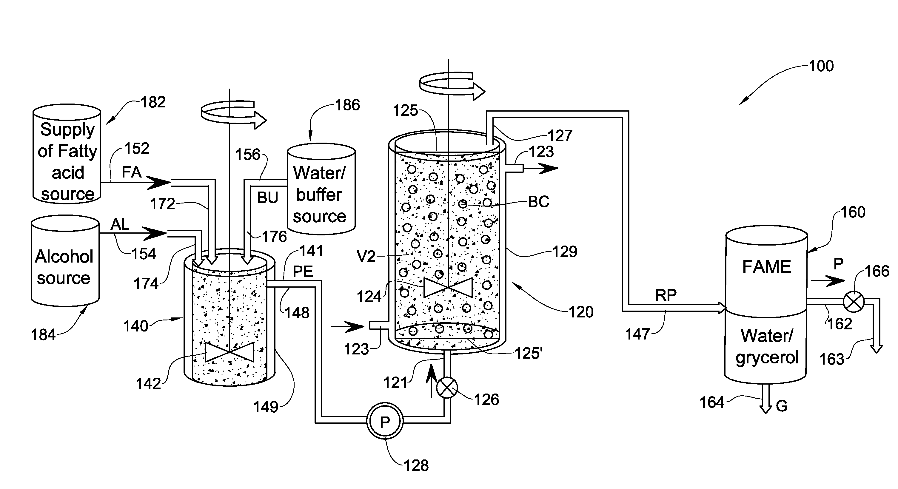
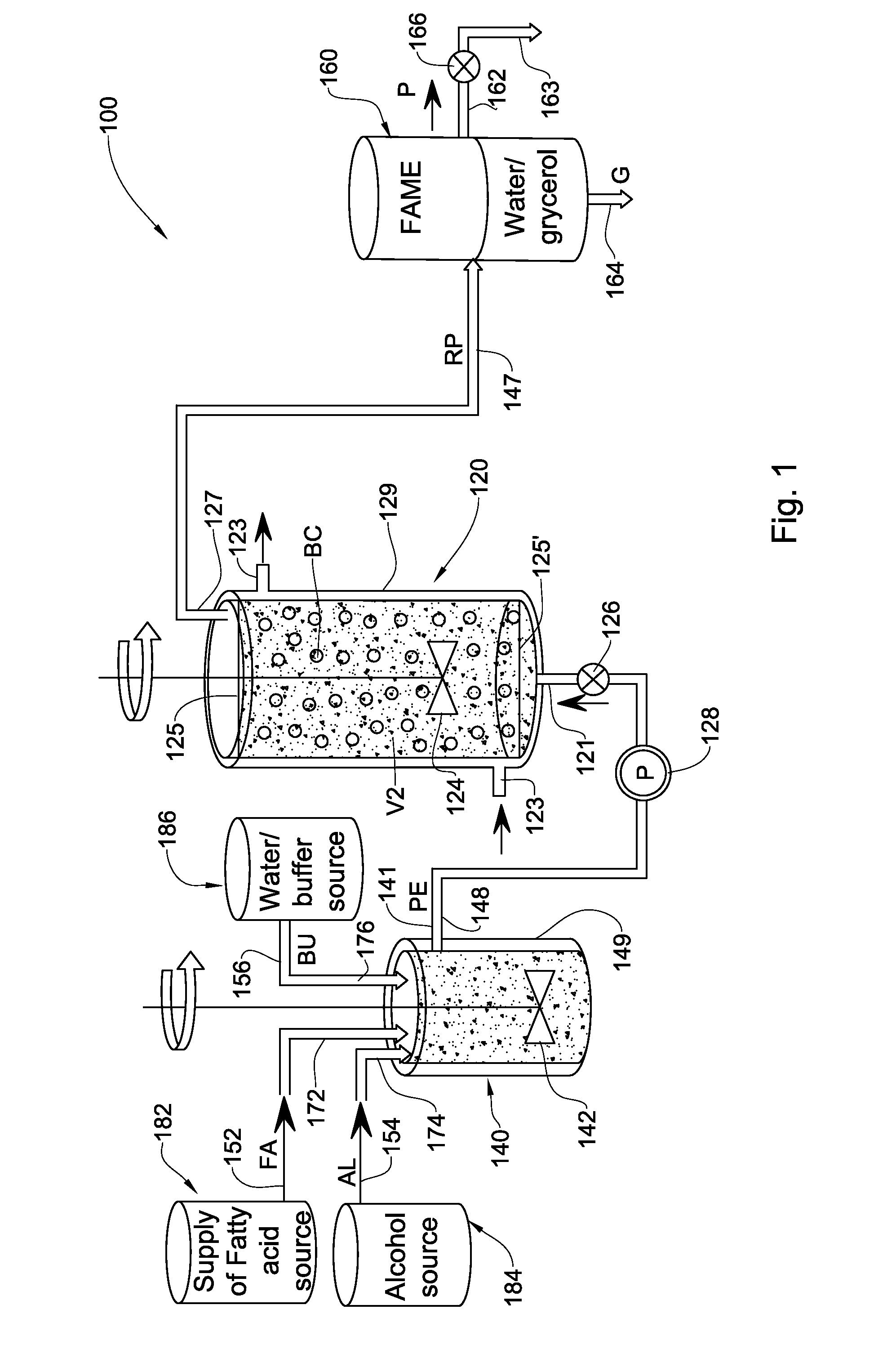
- Description
- Claims
- Application Information
AI Technical Summary
Benefits of technology
Problems solved by technology
Method used
Image

Examples
example 1
[0161]In this example, three processing systems were tested for a period extending to not less than 262 days.
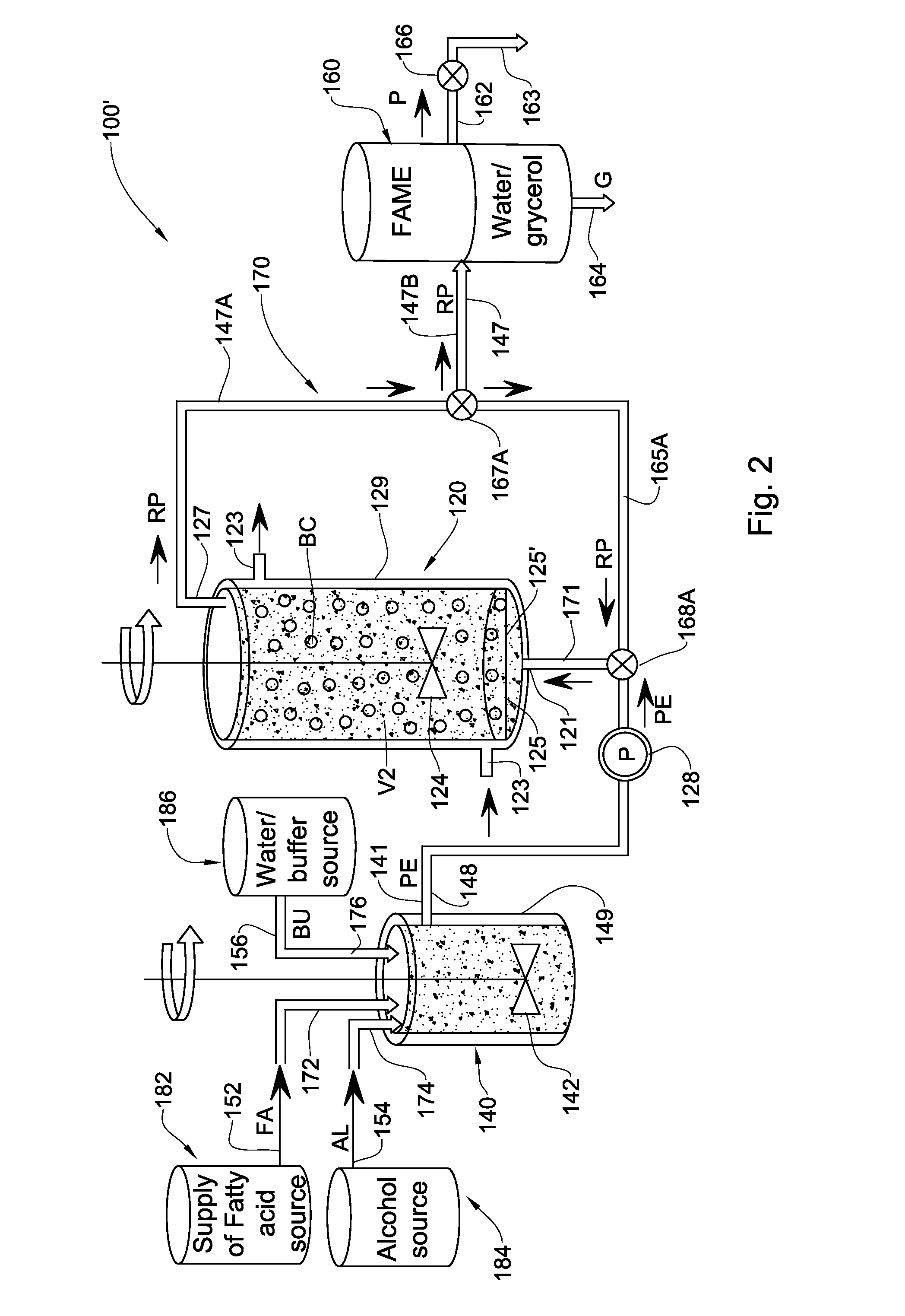
[0162]The first system (herein Example 1(a)) was based on the embodiment of the processing system 100′ illustrated in FIG. 2 with flow through the reactor vessel 120 in a direction generally opposed to gravity (bottom to-top), and operated at a flow rate of 20 ml / min throughput through the processing system.
[0163]The second system (herein Example 1(b)(i)) served as a control, and was based on a processing system similar to the system 100 of FIG. 1, but with the flow through the reactor vessel in a direction generally aligned with gravity (top-to bottom), rather than in a direction generally opposed to gravity (bottom to-top), and operated at a flow rate of 20 ml / min throughput through the respective processing system.
[0164]The third system (herein Example 1(b)(ii)) also served as a control, and was based on a processing system similar to the second system (i.e., with the flow...
example 1 (
Example 1(b(ii))
[0175]The system, reaction conditions and continuous reaction mode of operation used for this example was similar to that of Example 1(b)(i), mutatis mutandis, the only differences being that in Example 1(b)(ii) an emulsified reaction medium (prepared emulsion) containing soybean oil (80% wt), methanol (15%) and 0.1M sodium bicarbonate solution (5%) was continuously fed into the reactor vessel at a flow rate of 10 ml / min rather than 20 ml / min (provided by example 1(b(i)) or example 1(a)).
[0176]Table 1, column 4 shows the conversion of feedstock to fatty acid methyl esters in the above system at a number of days during the 262 day trial
TABLE 1The conversion of feedstock to fatty acid methyl esters in acontinuous hybrid stirred- and expanded-bed reactor withtime VS. control reactor vessel at the same flow rate andat reduced flow rate.Conversion (%)hybrid stirred- andConversion (%)Conversion (%)expanded-bedControl reactorControl reactorreactor at flow rateat flow rate o...
example 2
Second Stage Transesterification / Esterification Reaction Using the Effluent of the First Stage
[0177]In this example, three processing systems were tested for a period extending to not less than 121 days.
[0178]The first system (herein Example 2(a)) was based on the system 200′ of FIG. 5 with flow thorough the reactor vessel 120 and in the auxiliary reactor vessel 220 was in a direction generally opposed to gravity (bottom to-top), and operated at a flow rate of 20 ml / min throughput through the system 200′.
[0179]The second system (herein Example 2(b)(i)) served as a control, and was based on a processing system similar to the system 200′ of FIG. 5, but with the flow through the reactor vessel 100, and in the auxiliary reactor vessel 220 being in a direction generally aligned with gravity (top-to bottom), rather than in a direction generally opposed to gravity (bottom to-top), and operated at a flow rate of 20 ml / min throughput through the respective system.
[0180]The third system (here...
PUM
 Abstract
Description
Claims
Application Information