System for manufacturing a crystalline material by directional crystallization provided with an additional lateral heat source

a technology of directional crystallization and lateral heat source, which is applied in the direction of crystal growth process, photovoltaic energy generation, electrical equipment, etc., can solve the problems of increasing the difficulty in controlling the heat flux in the furnace, the limited czochralski growth technique, and the side walls of the crucible, so as to facilitate the fabrication of crystal ingots

Inactive Publication Date: 2014-07-10
COMMISSARIAT A LENERGIE ATOMIQUE ET AUX ENERGIES ALTERNATIVES
View PDF2 Cites 3 Cited by
  • Summary
  • Abstract
  • Description
  • Claims
  • Application Information

AI Technical Summary

Benefits of technology

[0014]It has also been observed that a requirement exists to provide a method that facilitates fabrication of crystal ingots with a low crystallographic defect concentration.

Problems solved by technology

However, it is important to note that the Czochralski growth technique is usually limited to formation of cylindrical ingots which is particularly problematic for use in the photovoltaic field where it is important to increase the effective surface of the photovoltaic panel.
However, the use of a crucible results in an increased difficulty in control of the heat fluxes in the furnace.
The side walls of the crucible increase the risks of germination of defects (spurious crystals, twin crystals) in the final ingot.
The crystalline defects degrade the crystallographic quality of the materials used in photovoltaic panels which results in a decrease of the energy conversion efficiency of the final photovoltaic device.

Method used


Image

  • System for manufacturing a crystalline material by directional crystallization provided with an additional lateral heat source
  • System for manufacturing a crystalline material by directional crystallization provided with an additional lateral heat source

Examples


Embodiment Construction

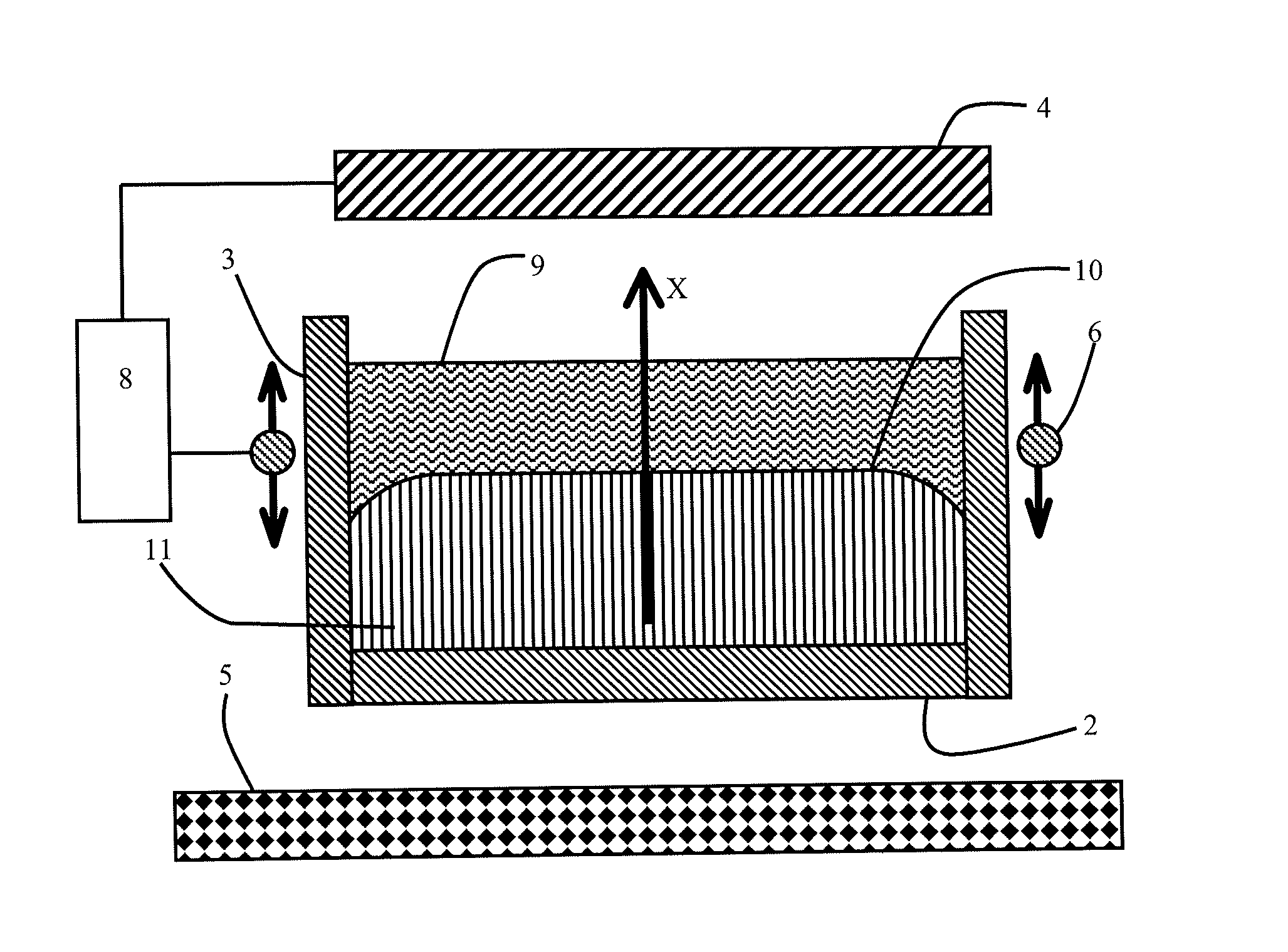
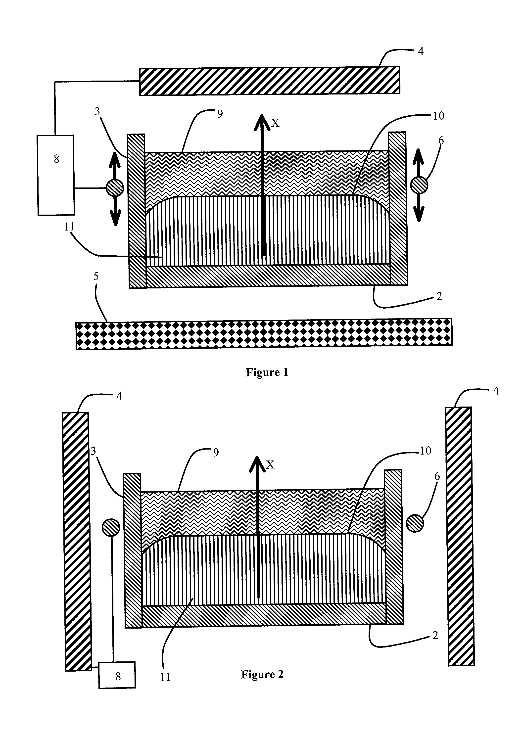
[0022]The directional solidification system illustrated in FIG. 1 comprises a crucible 1 provided with a bottom 2 and with side walls 3. The bottom of crucible 1 can be of any shape. For example purposes, the cross-section (i.e. the shape formed by bottom 2 of crucible 1) can be square, rectangular or cylindrical. In preferential manner, crucible 1 presents a rectangular or square cross-section in order to facilitate production of photovoltaic panels presenting a good occupation of the available surface by the crystalline substrate.

[0023]Side walls 3 are perpendicular to bottom 2 of crucible 1 or appreciably perpendicular to bottom 2. Crucible 1 is made from a material that is resistant to the high temperatures to which it is subjected during the melting and solidification phases. In preferential manner, crucible 1 is made from silica, but it can also be made from graphite, silicon carbide or a mixture of these materials.

[0024]Crucible 1 is tightly sealed with respect to the materia...


PUM

PropertyMeasurementUnit
distanceaaaaaaaaaa
distanceaaaaaaaaaa
distanceaaaaaaaaaa

Abstract

The crystallization system includes a crucible provided with a bottom and with side walls designed to contain the material to be solidified and a device for creating a main thermal gradient inside the crucible in a perpendicular direction to the bottom of the crucible. An additional inductive heating device is arranged at the level of the side walls of the crucible facing the liquid material and without overlapping with the solid phase. This additional inductive heating device is configured to heat a part of the crystalline material located in the vicinity of the triple contact line between the liquid material, the solidified material and the crucible so that the interface between the liquid material and the solidified material forms a convex meniscus in the vicinity of the triple contact line.

Description

BACKGROUND OF THE INVENTION[0001]The invention relates to a system and method for performing fabrication of a crystalline material by directional solidification. The invention applies in particular to semiconductor materials having a higher electric conductivity in liquid phase than in solid phase.STATE OF THE ART[0002]The silicon used in the photovoltaic industry is for the most part crystallized silicon of multicrystalline structure, i.e. with single-crystal grains without a fixed orientation with respect to one another and surrounded by grain boundaries. A sector using single-crystal silicon also exists, i.e. a single grain forms the silicon ingot. Growth of this type of material is achieved for example in a crucible in a crystallization furnace of Bridgman type or by means of the Czochralski growth technique.[0003]A large part of the silicon used in the photovoltaic industry is produced using the Czochralski technique. However, it is important to note that the Czochralski growth...

Claims


Application Information

Patent Timeline
Patent Type & Authority Applications(United States)
IPC IPC(8): C30B11/00C30B35/00
CPCC30B11/003C30B35/00C30B11/008C30B28/06C30B33/02H01L31/182Y02E10/546Y02P70/50Y10T117/1092C30B11/007C30B29/06
Inventor GARANDET, JEAN-PAULJOUINI, ANISPELLETIER, DAVID
Owner COMMISSARIAT A LENERGIE ATOMIQUE ET AUX ENERGIES ALTERNATIVES
Why Eureka
Try Eureka