
Sound transducer and microphone using same

a technology of sound transducer and microphone, applied in the field of acoustic transducers, can solve the problems of deterioration of sound quality, difficulty for low-sensitivity microphones to detect small sound with high quality, variation and mismatching of acoustic characteristics of chips, etc., and achieve the effect of reducing the variation between chips

Active Publication Date: 2014-07-10
ORMON CORP +1
View PDF1 Cites 17 Cited by
  • Summary
  • Abstract
  • Description
  • Claims
  • Application Information

AI Technical Summary

Benefits of technology

This configuration enhances the detectable sound pressure level, reduces THD, and improves sound quality by minimizing variations and mismatching in acoustic characteristics, while also simplifying the manufacturing process and reducing chip size.

Problems solved by technology

This is because attempting to detect a large sound by the microphone results in generation of a harmonic distortion in an output signal, thereby leading to deterioration of sound quality.
This is because the high-sensitivity microphone tends to output a large signal and therefore is likely to cause the THD.
However, it is difficult for the low-sensitivity microphone to detect a small sound with high quality.
However, according to the above configuration described in each of Japanese Unexamined Patent Publication No. 2008-245267 and U.S. Patent Application Publication No. 2007 / 0047746, the acoustic sensors are formed independently of one another, and therefore there occur a variation and mismatching in their acoustic characteristics.
Since the acoustic characteristics such as frequency characteristics and phases are affected by the back chamber and the vent hole, mismatching in the acoustic characteristics occurs in the chip.

Method used


Image

  • Sound transducer and microphone using same
  • Sound transducer and microphone using same
  • Sound transducer and microphone using same

Examples


first embodiment

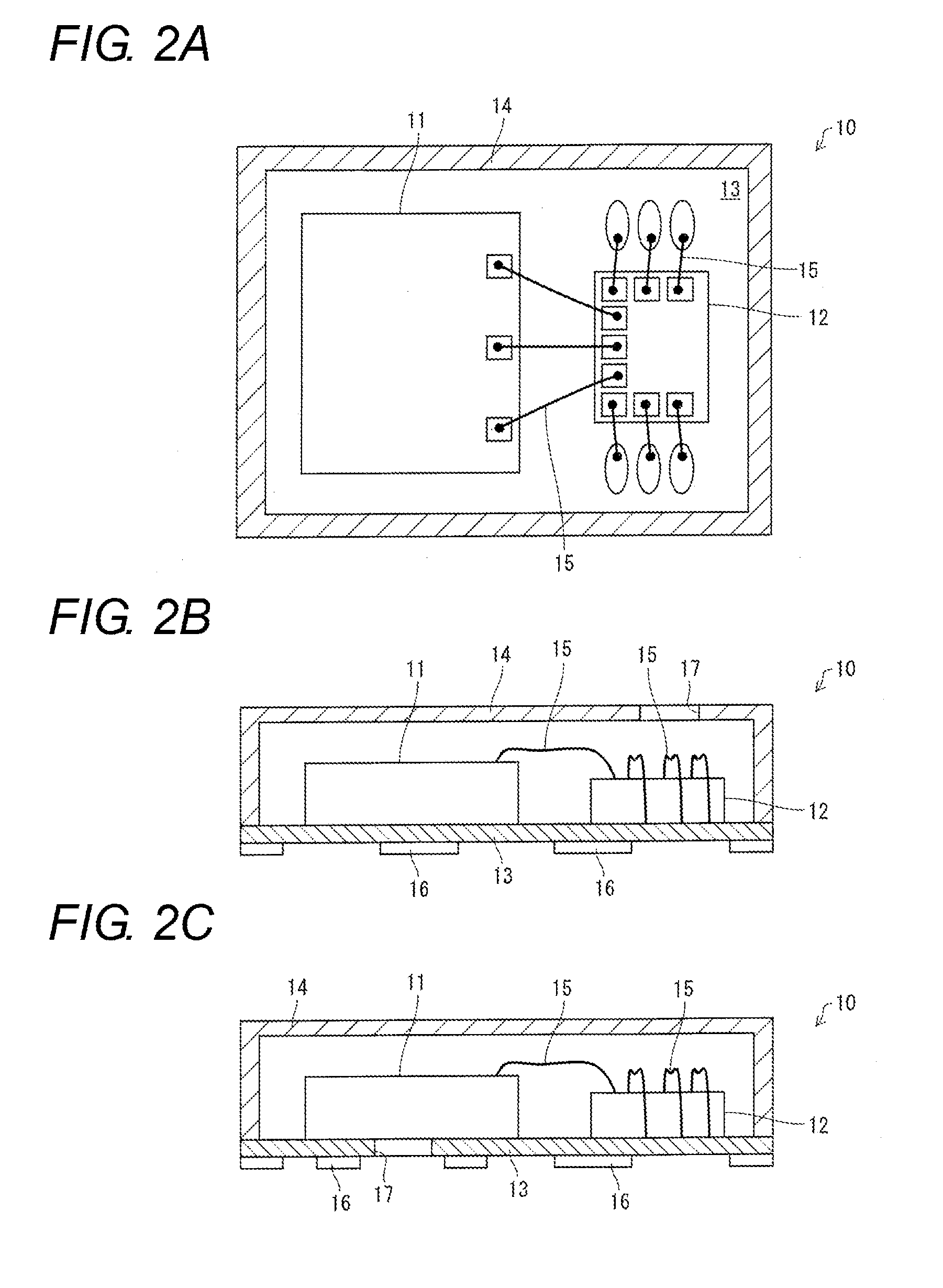
[0031]The following describes an embodiment of the present invention with reference to FIGS. 1A to 3. FIGS. 2A to 2C show a schematic configuration of a MEMS microphone of this embodiment. FIG. 2A is a plan view showing the MEMS microphone whose upper portion is cut away. FIGS. 2B and 2C are front views showing the MEMS microphones whose front portions are cut away. Note that FIG. 2C is a modification of the configuration shown in FIG. 2B.

[0032]As shown in FIG. 2A, the MEMS microphone 10 includes an acoustic sensor (acoustic transducer) 11, an ASIC 12, a wiring board 13, and a cover 14.

[0033]The acoustic sensor 11 detects a sound wave and coverts the sound wave into electrical signals (detection signals). The acoustic sensor 11 is a MEMS chip manufactured by using a MEMS technique. The ASIC 12 is an integrated circuit (IC) that has a power supply function to supply power to the acoustic sensor 11 and a signal processing function to appropriately process the electrical signal from th...

second embodiment

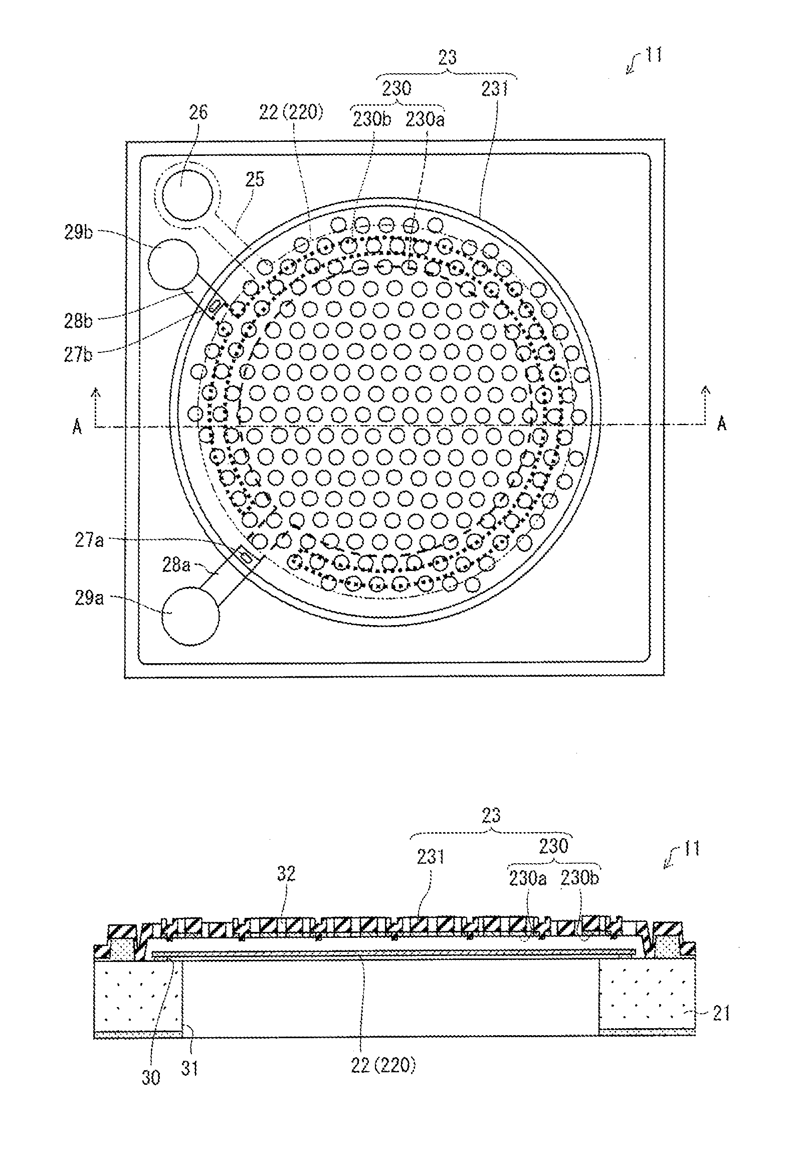
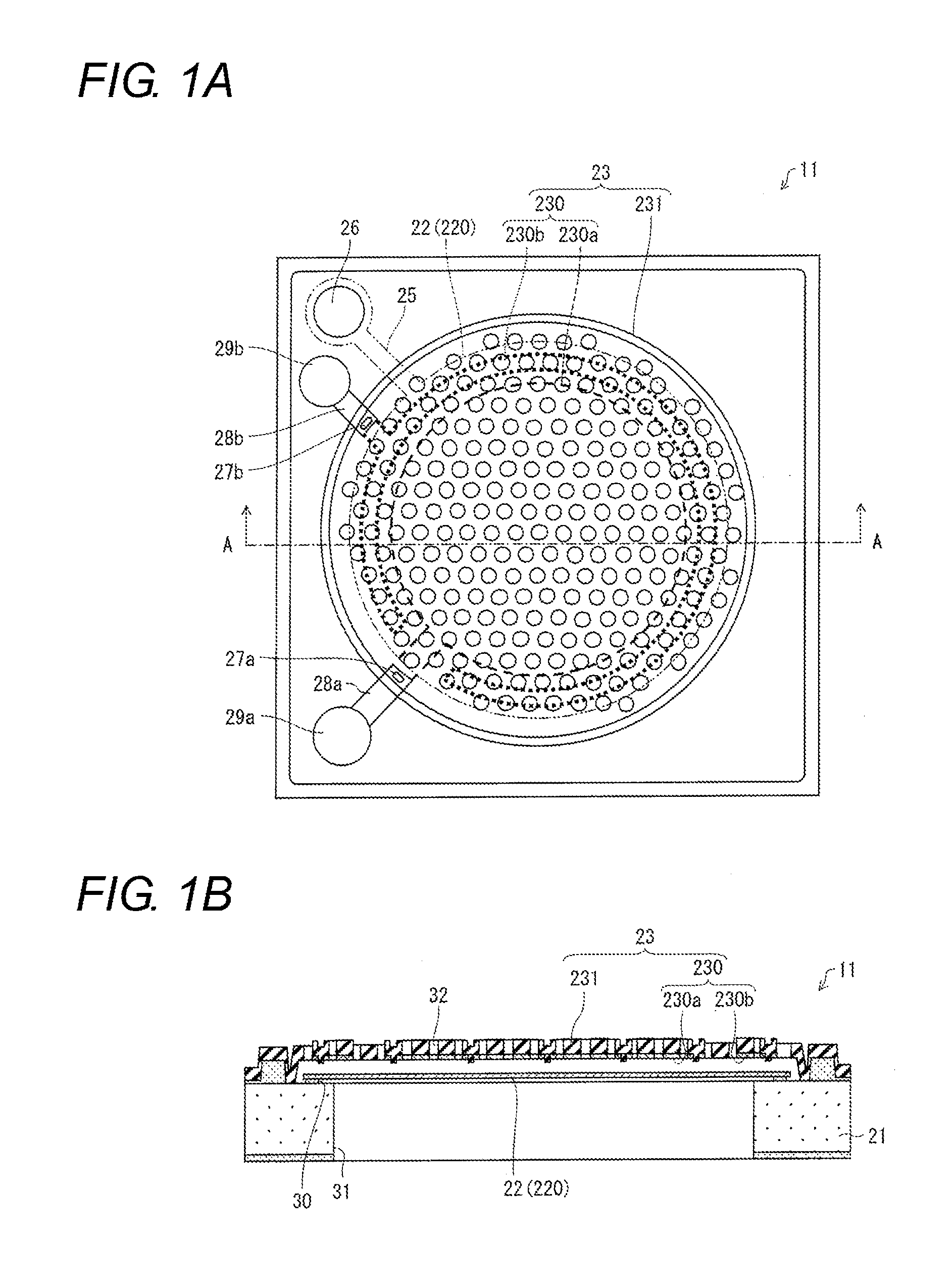
[0067]Next, a description is made of another embodiment of the present invention with reference to FIGS. 4A and 4B. FIGS. 4A and 4B show a schematic configuration of an acoustic sensor 11 according to this embodiment; where FIG. 4A is a plan view of the acoustic sensor 11, and FIG. 4B is a cross-sectional view of the acoustic sensor 11, taken along line B-B of FIG. 4A and viewed in an arrow direction thereof.

[0068]The acoustic sensor 11 shown in FIGS. 4A and 4B is different from the acoustic sensor 11 shown in FIGS. 1A and 1B in that the insulating layer 30 is not present and an edge of a vibrating membrane 22 is not fixed to a semiconductor substrate 21, and that protruding portions 232 extending from a protecting membrane 231 of a fixed membrane 23 to the vibrating membrane 22, are provided so as to be apart from each other along a peripheral electrode 230b. The acoustic sensor 11 shown in FIGS. 4A and 4B is similar to the acoustic sensor 11 shown in FIGS. 1A and 1B in other compo...

third embodiment

[0070]Next, a description is made of still another embodiment of the present invention with reference to FIG. 5 and FIG. 6. FIG. 5 is a plan view showing a schematic configuration of an acoustic sensor 11 according to this embodiment. Note that, in FIG. 5, the protecting membrane 231 of the fixed membrane 23 is omitted.

[0071]The acoustic sensor 11 shown in FIG. 5 is different in the shape of the vibrating membrane 22 from the acoustic sensor shown in FIGS. 1A and 1B, and therefore, is different therefrom also in the shape of the fixed membrane. Note that other components of the acoustic sensor 11 shown in FIG. 5 are similar to those of the acoustic sensor shown in FIGS. 1A and 1B.

[0072]The vibrating membrane 22 of the acoustic sensor 11 shown in FIGS. 1A and 1B is circular and has the edge portion fixed to the substrate 21. On the other hand, as shown in FIG. 5, the vibrating membrane 22 of the acoustic sensor 11 of this embodiment has a base portion having a substantially square sh...


PUM


Abstract

Provided is an acoustic transducer including: a semiconductor substrate; a vibrating membrane, provided above the semiconductor substrate, including a vibrating electrode; and a fixed membrane, provided above the semiconductor substrate, including a fixed electrode, the acoustic transducer detecting a sound wave according to changes in capacitances between the vibrating electrode and the fixed electrode, converting the sound wave into electrical signals, and outputting the electrical signals. At least one of the vibrating electrode and the fixed electrode is divided into a plurality of divided electrodes, and the plurality of divided electrodes outputting the electrical signals.

Description

BACKGROUND[0001]1. Technical Field[0002]The present invention relates to an acoustic transducer that converts a sound wave into electrical signals, and to a microphone including the acoustic transducer. In particular, the present invention relates to a micro-sized acoustic transducer, which is fabricated by using a MEMS (Micro Electro Mechanical System) technology, and the like.[0003]2. Description of the Related Art[0004]Conventionally, an ECM (Electret Condenser Microphone) has been widely used as a miniature microphone mounted on a cellular (mobile) phone and the like. However, the ECM is weak against heat, and a MEMS microphone is superior to the ECM in terms of digitalization, miniaturization, enhancement of functionality / multi-functionality, and power saving. Accordingly, at present, the MEMS microphone is becoming widespread.[0005]The MEMS microphone includes a capacitor-type acoustic sensor (acoustic transducer) that detects a sound wave and converts the detected sound wave ...

Claims


Application Information

Patent Timeline
Patent Type & Authority Applications(United States)
IPC IPC(8): B81B3/00
CPCB81B3/0021H04R1/086H04R3/005H04R19/005H04R19/016H04R19/04H04R31/00H04R2499/11H04R1/023H04R3/00H04R2201/003
Inventor KASAI, TAKASHISATO, SHOBUUCHIDA, YUKIPADOVANI, IGINODAVID, FILIPPOCONTI, SEBASTIANO
Owner ORMON CORP
Learn More