Cutting Insert and Method for Production Thereof

a cutting insert and cutting technology, applied in the field of cutting inserts, can solve the problems of cutting insert wear resistance, cracks and fractures in the coating perpendicularly, adhesion problems, coating spalling, etc., and achieve excellent wear resistance, high wear resistance, and loss of toughness

Active Publication Date: 2014-07-10
WALTER AG
View PDF8 Cites 51 Cited by
  • Summary
  • Abstract
  • Description
  • Claims
  • Application Information

AI Technical Summary

Benefits of technology

[0004]The effect of the inherent stresses in the coating and in the substrate body can be without a considerable influence on the properties of the cutting insert, but they can also have considerable advantageous or disadvantageous effects on the wear resistance of the cutting insert. Tension inherent stresses which exceed the tensile strength of the respective material cause fractures and cracks in the coating perpendicularly to the direction of the tension inherent stress. In general a certain amount of compression inherent stress in the coating is desired as surface cracks are prevented or closed thereby and the fatigue properties of the coating and thus the cutting insert are improved. Excessively high compression inherent stresses however can lead to adhesion problems and spalling of the coating.
[0005]There are 3 kinds of inherent stresses: macrostresses which are almost homogenously distributed over macroscopic regions of the material, microstresses which are homogenous in microscopic regions like for example a grain, and non-homogenous microstresses which are also non-homogenous on a microscopic plane. From a practical point of view and for the mechanical properties of a cutting insert macrostresses are of particular significance.
[0006]Inherent stresses are usually specified using the unit Megapascal (MPa), wherein tension inherent stresses have a positive sign (+) and compression inherent stresses have a negative sign (−).
[0007]It is known that hard metal cutting tools which are coated with hard material layers like for example TiN, TiC, TiCN, TiAlN, Al2O3 or combinations thereof can have excellent wear resistance but they can rather fail in a situation involving thermomechanical alternating loading in interrupted cutting operations as for example in crankshaft milling, by virtue of a loss in toughness in relation to uncoated cutting tools or those which are coated by means of PVD methods. A similar consideration applies to turning working in an interrupted cutting mode or under disadvantageous cutting conditions (for example vibrations caused by the machine or the workpiece clamping). For such applications under disadvantageous conditions, hitherto CVD coatings with a limited layer thickness (rarely more than 10 μm) are used as the embrittlement of the cutting material, caused inter alia by tensile stresses, increases with the thickness of the CVD coating. Highly wear-resistant kinds of cutting materials in contrast frequently involve layer thicknesses of 20 μm or more, but they can only be used in a continuous cutting mode under advantageous conditions. In the case of cutting inserts for turning working of steel or cast iron therefore both high wear resistance and also high toughness are desired, these being two properties which frequently cannot be achieved at the same time.
[0008]DE-A-197 19 195 describes a cutting insert have a multi-layer coating which is deposited in a continuous CVD method at temperatures between 900° C. and 1100° C. The change in material in the multi-layer coating from one layer to the next occurs due to a change in the gas composition in the CVD method. The outermost layer (cover layer) comprises a single-phase or multi-phase layer of carbides, nitrides or carbonitrides of Zr or Hf, in which internal compression inherent stresses prevail. The subjacent layers comprise TiN, TiC or TiCN and without exception have internal tension inherent stresses. The compression inherent stress measured in the outer layer is between −500 and −2500 MPas. That is intended to improve fracture toughness.
[0009]To increase the compression inherent stresses in the coating on the substrate body of cutting inserts or other tools it is known for them to be subjected to a mechanical surface treatment. Known mechanical surface methods are brushing and jet blasting treatment. Jet blasting treatment involves directing a fine-grain jet blasting agent of grain sizes of up to about 600 μm by means of compressed air under increased pressure on to the surface of the coating. Such a surface treatment can reduce tension inherent stresses or compression inherent stresses in the outermost layer and also in the subjacent layers. In regard to jet blasting treatment a distinction is drawn between dry jet blasting treatment in which the fine-grain jet blasting agent is used in the dry condition and wet jet blasting treatment in which the granular jet blasting agent is suspended in a liquid.

Problems solved by technology

The effect of the inherent stresses in the coating and in the substrate body can be without a considerable influence on the properties of the cutting insert, but they can also have considerable advantageous or disadvantageous effects on the wear resistance of the cutting insert.
Tension inherent stresses which exceed the tensile strength of the respective material cause fractures and cracks in the coating perpendicularly to the direction of the tension inherent stress.
Excessively high compression inherent stresses however can lead to adhesion problems and spalling of the coating.
It is known that hard metal cutting tools which are coated with hard material layers like for example TiN, TiC, TiCN, TiAlN, Al2O3 or combinations thereof can have excellent wear resistance but they can rather fail in a situation involving thermomechanical alternating loading in interrupted cutting operations as for example in crankshaft milling, by virtue of a loss in toughness in relation to uncoated cutting tools or those which are coated by means of PVD methods.
A similar consideration applies to turning working in an interrupted cutting mode or under disadvantageous cutting conditions (for example vibrations caused by the machine or the workpiece clamping).
It is not possible to achieve an increase in the toughness of the tool.
If nonetheless there is a wish to increase the compression stress in the substrate even with thick layers, it is necessary to use very long dry jet blasting operations, which leads to an increase in lattice dislocations and can cause adhesion problems with the coating.

Method used


Image

  • Cutting Insert and Method for Production Thereof
  • Cutting Insert and Method for Production Thereof
  • Cutting Insert and Method for Production Thereof

Examples


example 1

[0066]WC / Co hard metal substrate bodies (indexable cutting bits of various compositions (HM1, HM2, HM3, HM4, HM5 and HM6) were coated in a CVD method in the layer sequence TiN-MT-TiCN-α-Al2O3—HT-TiCN with various layer thicknesses for the individual layers. A thin (2O3 layer. All coatings were produced in a CVD reactor of Bernex BPX325S type with a radial gas flow.

[0067]The MT-TiCN layer was deposited at a pressure of 90 mbars and with the following gas concentrations (percentages in relation to the gases in the CVD method denote % by volume): 2.0% TiCl4, 0.5% CH3CN, 10% N2, 87.5% H2.

[0068]A thin (2O3 layer in three process steps.

[0069]1. Ti(C,N)—duration: 20 min, temperature: 1000° C., pressure: 500 mbars, gas concentrations: 5% CH4, 2% TiCl4, 25% N2, balance H2

[0070]2. (Ti,Al)(C,N,O)—duration: 15 min, temperature: 1000° C., pressure: 75 mbars, gas concentrations: 5% CO, 1% AlCl3, 2% TiCl4, 25% N2, balance H2

[0071]3. (Ti,Al)(C,N,O)—duration: 5 min, temperature: 1000° C., pressure...

example 2

Cutting Machining Tests

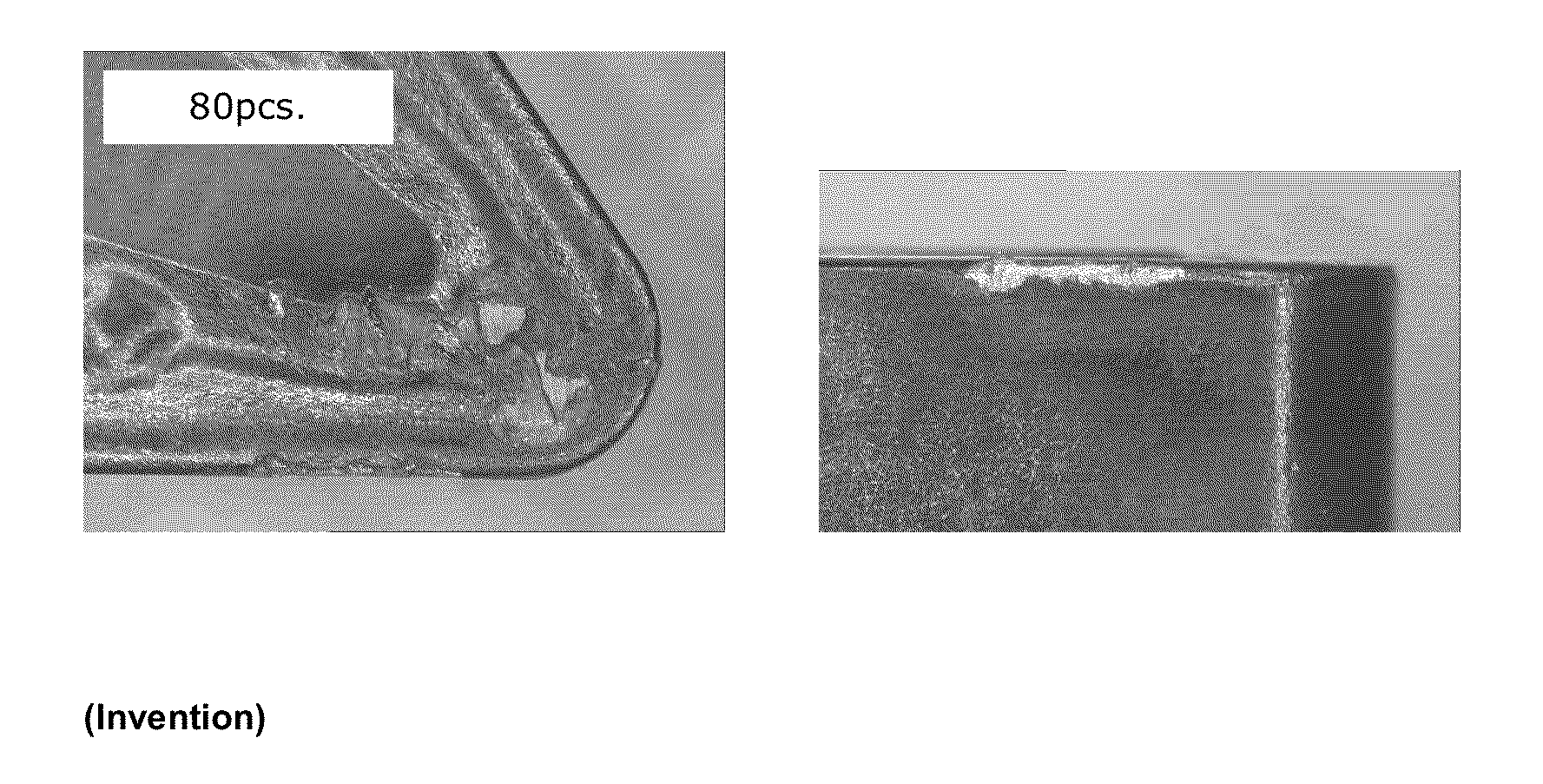
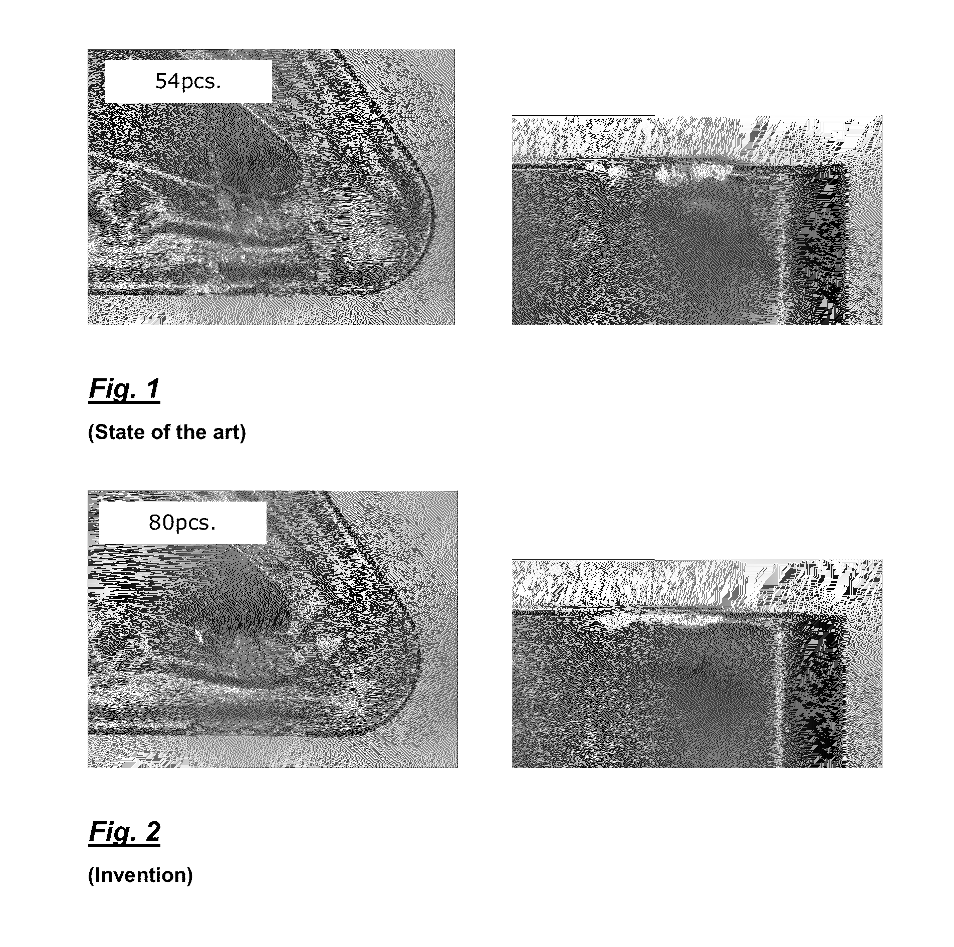
[0091]The cutting bits produced in accordance with Example 1 were used to subject camshafts to external machining in the interrupted cutting mode in accordance with the following test parameters:[0092]Work piece: camshaft[0093]Material: 16MnCr5 (Rm=600−700N / mm2)[0094]Machining; Lengthwise turning in the interrupted cutting mode; wet machining[0095]Cutting data: vc=220 m / min[0096]f=0.4 mm[0097]ap=2.5 mm[0098]Tool geometry: DNMG150608-NM4[0099]Tool life: State of the art: cutting insert 11 according to Table 5: 54 components[0100]Invention: cutting insert 14 according to Table 5: 80 components

[0101]FIG. 1 shows the tool according to the state of the art (cutting insert 11 of Table 5) after the machining of 54 components. After the end of the tool life both crater wear and also notch wear and break-out phenomena at the cutting edge are to be seen. Crater wear is a typical form of wear when turning steel materials, occurring because of a lack of wear resistance at...

example 3

Cutting Machining Tests

[0103]Cutting bits produced according to Example 1 were subjected to the so-called strip turning test (test using a severely interrupted cutting mode). In that test the toughness characteristic of indexable cutting bits is investigated, by a shaft equipped with four strips of heat-treatable steel being machined in an external lengthwise turning process. The strips which in that case are subjected to cutting machining represent only a part of the periphery so that a severely impacting action takes place on the tool cutting edges. The life of the tool is determined as the number of entries into the workpieces until failure of the cutting edge due to fracture (impact count).[0104]Material: 42CrMo4; Rm=800 N / mm2 [0105]Machining: Lengthwise turning in the interrupted cutting mode; dry machining[0106]Cutting data: vc=170[0107]f=0.32 mm[0108]ap=2.5 mm[0109]Tool geometry: CNMG120412-NM4[0110]Tool life / impact count (respective mean value from 6 tested cutting inserts):...


PUM

PropertyMeasurementUnit
thicknessaaaaaaaaaa
thicknessaaaaaaaaaa
thicknessesaaaaaaaaaa

Abstract

Cutting insert made of hard metal, cermet or ceramic substrate body with multi-layer coating applied thereto by CVD methods. The coating has a total thickness of 5 to 40 μm and, starting from the substrate surface, has one or more hard material layers, an alpha aluminium oxide (α-Al2O3) layer of a layer thickness of 1 to 20 μm and optionally at least portion-wise over the α-Al2O3 layer one or more further hard material layers as decorative or wear recognition layers. The α-Al2O3 layer has a crystallographic preferential orientation characterised by a texture coefficient TC (0 0 12)≧5 for the (0 0 12) growth direction.The α-Al2O3 layer has an inherent stress in the region of 0 to +300 MPas, and the substrate within a region of 0 to 10 μm from the substrate surface has an inherent stress minimum in the region of −2000 to −400 MPas.

Description

SUBJECT OF THE INVENTION[0001]The invention concerns a coated cutting insert made of a hard metal, cermet or ceramic substrate body and a multi-layer coating which is applied thereto by means of CVD methods and which starting from the substrate surface has one or more hard material layers, over the hard material layers an alpha aluminium oxide (α-Al2O3) layer and optionally at least portion-wise over the α-Al2O3 layer one or more further hard material layers as decorative or wear recognition layers.BACKGROUND OF THE INVENTION[0002]Cutting inserts for material working, in particular for cutting metal working, comprise a hard metal, cermet or ceramic substrate body which in most cases is provided with a single-layer or multi-layer surface coating to improve the cutting and / or wear properties. The surface coatings comprise mutually superposed hard material layers of carbides, nitrides, oxides, carbonitrides, oxynitrides, oxycarbides, oxycarbonitrides, borides, boronitrides, borocarbide...

Claims


Application Information

Patent Timeline
Patent Type & Authority Applications(United States)
IPC IPC(8): B23B27/14C30B25/00B23C5/20
CPCB23B27/148C30B25/00B23C5/20C23C16/403C23C16/56C23C28/044C23C30/005Y10T428/24975
Inventor STIENS, DIRKRUPPI, SAKARIFUHRMANN, THOMAS
Owner WALTER AG
Why Eureka
Try Eureka