High-strength zn-al coated steel wire for bridges with excellent corrosion resistance and fatigue properties and method for manufacturing the same

Active Publication Date: 2012-03-22
NIPPON STEEL CORP
View PDF3 Cites 8 Cited by
  • Summary
  • Abstract
  • Description
  • Claims
  • Application Information

AI Technical Summary

Benefits of technology

[0017]In accordance with one embodiment of the present invention, provided is a Zn—Al coated steel wire for bridges which can solve the problem of the Zn—Al coated steel wire with excellent corrosion resistance manufactured by a 1-bath method, refine the Al-rich phase (Al-rich primary phase) of a coating layer, inhibit growth of an alloy layer in the interface between the coating layer and the steel wire, and thus exhibit a corrosion resistance and fatigue properties considerably higher than conventional Zn—Al coated steel wire. More specifically, in one embodiment of the present invention, provided is a high-strength Zn—Al coated steel wire with excellent corrosion resistance and fatigue properties, for bridges such as suspension bridges and cable-stayed bridges, which has a wire diameter of 4 mm to 8 mm, a tensile strength of 1500 MPa to 1800 MPa, over 1800 MPa to 2000 MPa, or over 2000 MPa, and has a steel wire surface coated with Zn—Al. According to other embodiments of the present invention, provided are a method for manufacturing the coated steel wire and the wire rod used for manufacturing the coated steel wire.Means for Solving the Problem
[0036]According to the present invention, high-strength Zn—Al coated steel wire for bridges with excellent corrosion resistance and fatigue properties can be efficiently provided, and, at the same time, remarkable industrial contribution can be realized, for example, prolongment of lifetime can be imparted to the steel wires for bridges.

Problems solved by technology

However, it is difficult to treat the steel wire with the hot-dip Zn—Al alloy coating by using the same process as the conventional galvanizing.
The cause is that an ammonium chloride flux used for manufacturing galvanized steel wire is decomposed in the molten Zn—Al bath containing Al.
For example, when a hot-dip Zn—Al coated steel wire is manufactured by a flux method using ammonium chloride, defects such as non-coating may occur.
However, such a 2-bath method is disadvantageous in terms of the necessity of preparing two types of molten coating baths, an increase in required processing and an increase in manufacturing costs.
In addition, in the 2-bath method, a Fe—Zn alloy layer formed in the interface between the coating and the steel substrate grows further when the galvanized steel wire is immersed in molten Zn—Al bath at about 450° C., and then the alloy layer thickens, which causes a deterioration in fatigue properties and workability.
However, this method also is disadvantageous in terms of an increase in required processing and an increase in manufacturing costs.
However, this method also involves an increase in the overall processing and cannot avoid growth of the alloy layer formed in the interface between the coating and the steel substrate.

Method used


Image

  • High-strength zn-al coated steel wire for bridges with excellent corrosion resistance and fatigue properties and method for manufacturing the same
  • High-strength zn-al coated steel wire for bridges with excellent corrosion resistance and fatigue properties and method for manufacturing the same
  • High-strength zn-al coated steel wire for bridges with excellent corrosion resistance and fatigue properties and method for manufacturing the same

Examples


example 1

[0127]A steel material containing 0.77% of C, 0.22% of Si, 0.78% of Mn, 0.006% of P, 0.008% of S, 0.031% of Al, and the balance consisting of Fe and unavoidable impurities was hot-rolled to obtain wire rod. The wire rod was cooled in salt bath at 525° C. just after hot-rolling as patenting. In addition, the wire rod was cold-drawn to obtain a steel wire with a wire diameter of 4.9 mm. The steel wire was degreased, pickled with acid, immersed in flux aqueous solution at 60° C. for 10 sec, dried and then coated under conditions as shown in Tables 1 to 3 below. Also, the coating thickness was controlled to be 50 μm by wiping.

[0128]In addition, a flux used for Zn—Al coating herein was aqueous solution having a total flux concentration of 15% and a pH of 1.0, and was controlled to 30% to 40% of Zn2+ ions, 8% to 12% of K+ ions, 2% to 3% of Sn2+ ions, and 45% to 50% of the total amount of Cl− and F− ions. In addition, 7% NH4Cl aqueous solution was used as a flux for galvanizing.

[0129]Also,...

example 2

[0150]The chemical components of a test material are shown in Table 4. The test material was hot-rolled and then directly cooled in salt bath just after hot-rolling to perform patenting. Also, a steel A shown in Table 4 has the same component as in Example 1. The obtained wire rod was cold-drawn to obtain a high-carbon steel wire with a wire diameter of 4.5 mm to 7.3 mm, and hot-dip Zn—Al coating was performed by a 1-bath method. For comparison, 2-bath hot-dip Zn—Al coating (galvanizing and then hot-dip Zn—Al coating) and galvanizing were performed.

[0151][Table 4]

[0152]In Table 4, the symbol “-” means that an element is not intentionally added. An underlined value means that the value is out of the range of the present invention.

[0153]The hot-dip coating was carried out by degreasing the steel wire, pickling with acid, immersing in flux aqueous solution at 60° C. for 10 sec, drying and then immersing in molten coating bath with a predetermined composition for 5 sec to 15 sec. The te...

example 3

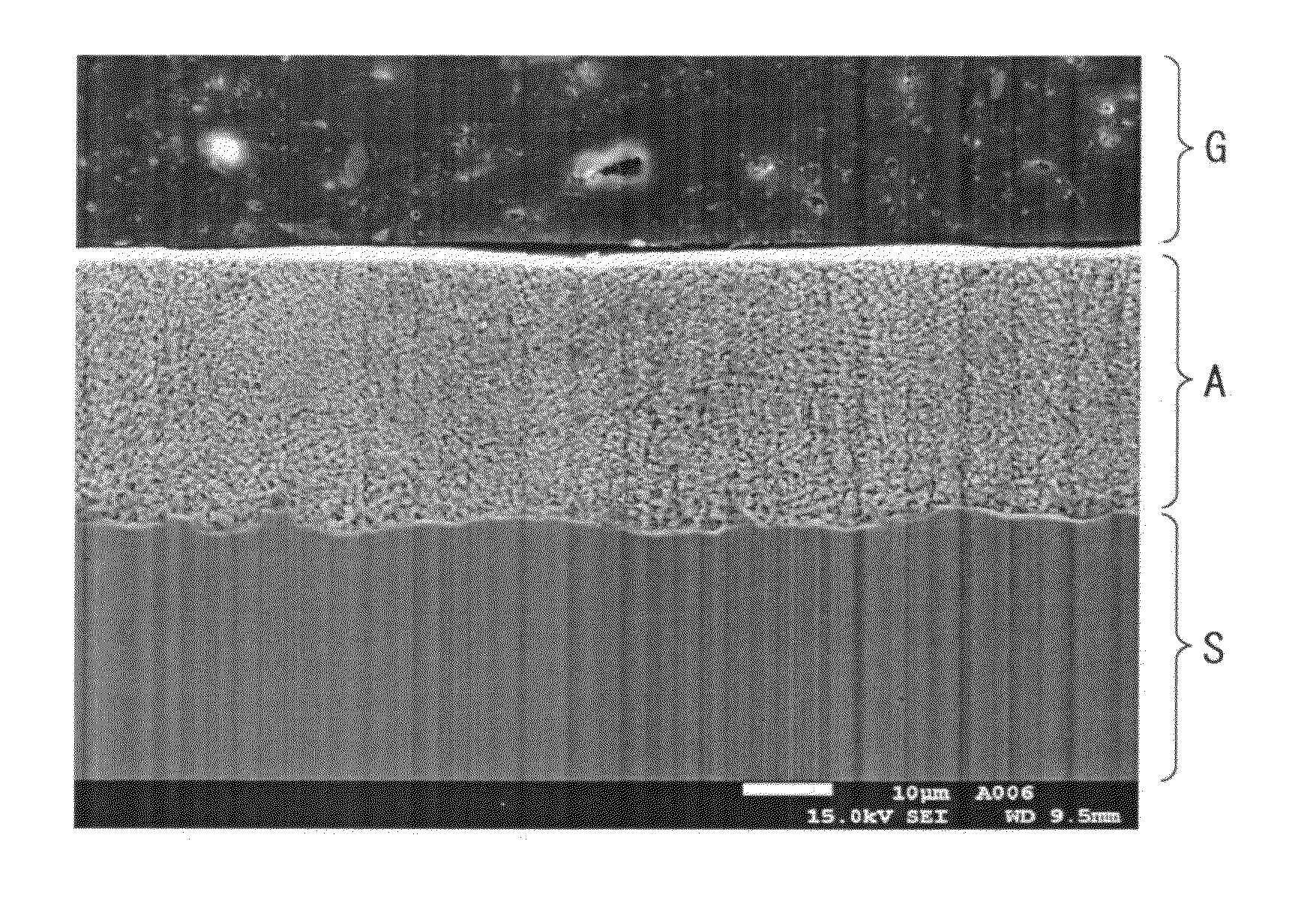
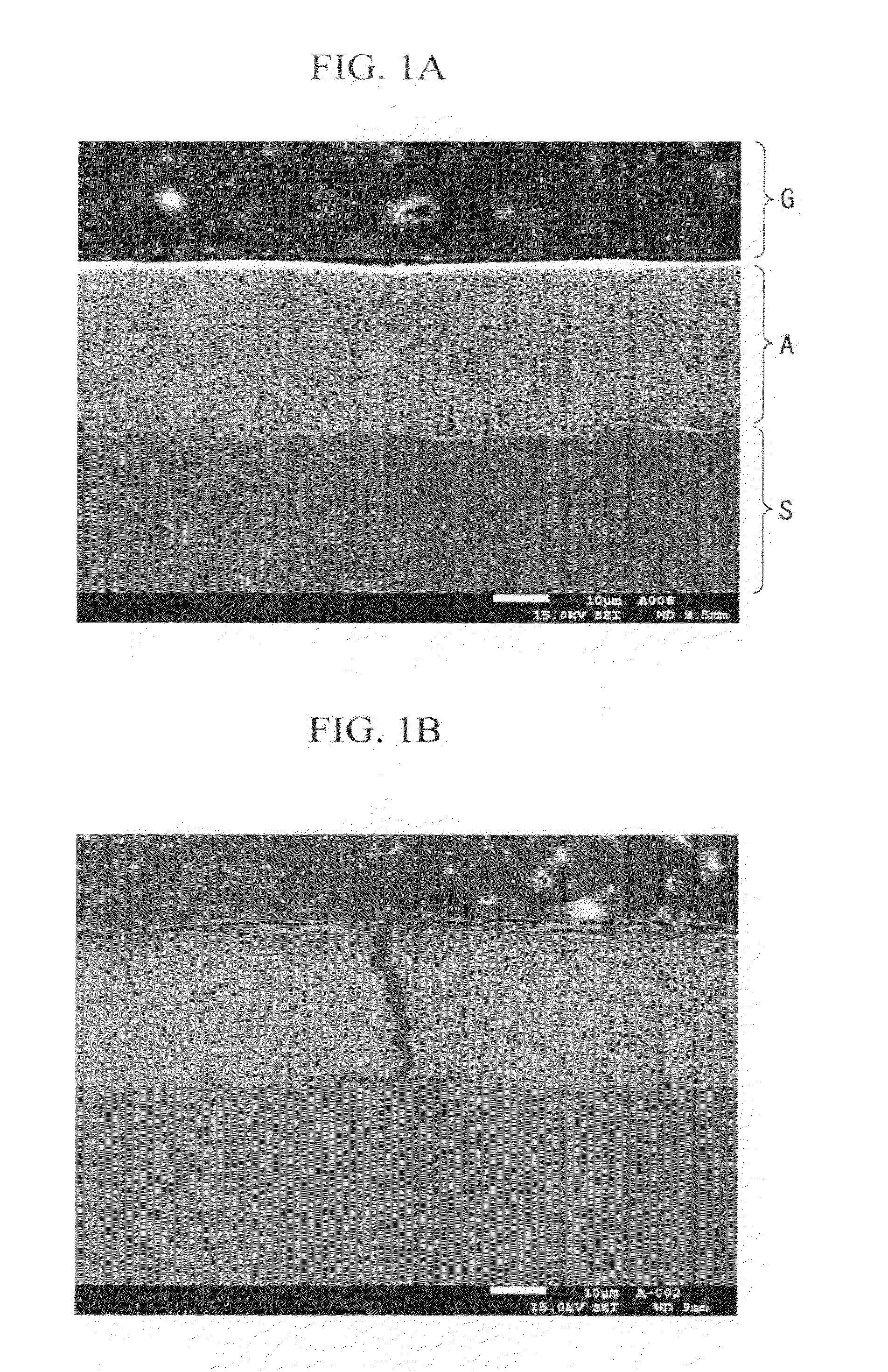
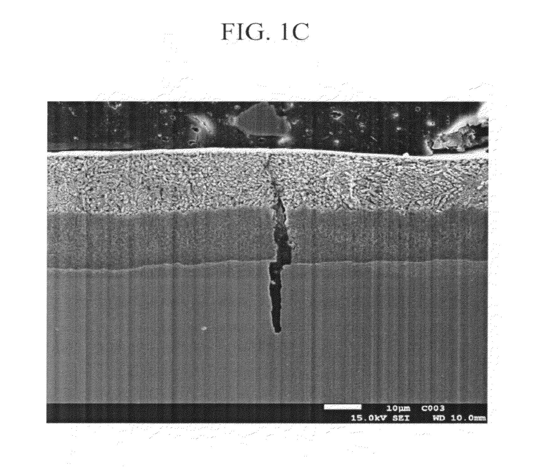
[0168]The chemical components of a test material associated with Example 3 are shown in Table 9. The test material was hot-rolled and then directly cooled in salt bath just after hot-rolling to perform patenting. The microstructure of the obtained wire rod was observed with SEM and TEM to measure the pearlite fraction and the cementite thickness thereof. The tensile strength was measured in accordance with JIS Z 2241. The difference in the tensile strength of the wire rod was determined by conducting the tensile test by using 36 test specimens in total sampled from three rings of the coil, and by calculating the difference between the maximum and minimum in the tensile strength. Table 10 shows the patenting temperature, the pearlite fraction and the cementite thickness of the wire rod, the tensile strength, and the difference in the tensile strength. Table 10 also shows a value calculated by the equation of 0.027×C.

[0169][Table 9]

[0170]In Table 9, an underlined value means that the ...


PUM

PropertyMeasurementUnit
Temperatureaaaaaaaaaa

Abstract

Disclosed is a high-strength Zn—Al coated steel wire for bridges with excellent corrosion resistance and fatigue properties, the Zn—Al coated steel wire includes: a steel wire; and a Zn—Al coating having a coating body layer and an Fe—Al alloy layer formed in an interface between a surface layer of the steel wire and the coating body layer, wherein a chemical composition of a core material of the steel wire includes, by mass %: C: 0.70% to 1.2%; Si: 0.01% to 2.5%; Mn: 0.01% to 0.9%; P: limited to 0.02% or less; S: limited to 0.02% or less; N: limited to 0.01% or less; and the balance including Fe and unavoidable impurities, wherein wire-drawn pearlite is most abundant microstructure among microstructures of the core material of the steel wire; wherein an average composition of the Zn—Al coating includes, by mass %, Al: 3.0 to 15.0%; and Fe: limited to 3.0% or less, and wherein the Fe—Al alloy layer has a thickness of 5 μm or less.

Description

TECHNICAL FIELD [0001]The present invention relates to a high-strength Zn—Al coated steel wire suitable for main cables of suspension bridges, cable-stayed bridges and the like, a method for manufacturing the same, and wire rod for the high-strength Zn—Al coated steel wire for bridges.[0002]This application claims the priority based on Japanese Patent Application Nos. 2009-151303 filed on Jun. 25, 2009, 2009-151304 filed on Jun. 25, 2009, and 2009-151438 filed on Jun. 25, 2009, the contents of which are incorporated herein by reference.RELATED ART [0003]Steel wire for bridges used for suspension bridges, cable-stayed bridges and the like are manufactured by patenting hot-rolled wire rod, followed by wire-drawing and surface-treating such as galvanizing. Here, patenting is a heat treatment to secure the strength of the steel wire and improve the cold workability of wire-drawing. Such patenting may be carried out by holding the wire rod under an environment of air (Stelmor method), or...

Claims


Application Information

Patent Timeline
IPC IPC(8): B32B15/01B21C43/00B32B15/02
CPCB32B15/013Y10T428/1266C21D1/607C21D9/525C21D2211/009C22C18/04C22C38/001C22C38/02C22C38/04C22C38/06C22C38/18C23C2/02C23C2/06C23C2/38C23C28/021Y10T428/12799C21D1/20C23C2/024C23C2/0224C22C38/44C22C38/46
Inventor SHIMODA, NOBUYUKITARUI, TOSHIMIKODAMA, JUNICHIKOSAKA, MAKOTOYAMASAKI, SHINGO
Owner NIPPON STEEL CORP
Why Eureka
Try Eureka