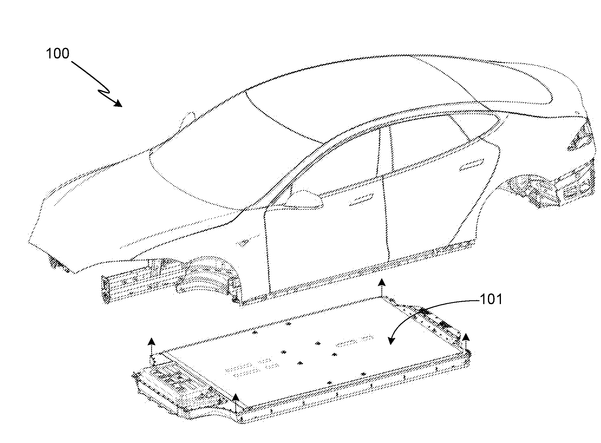
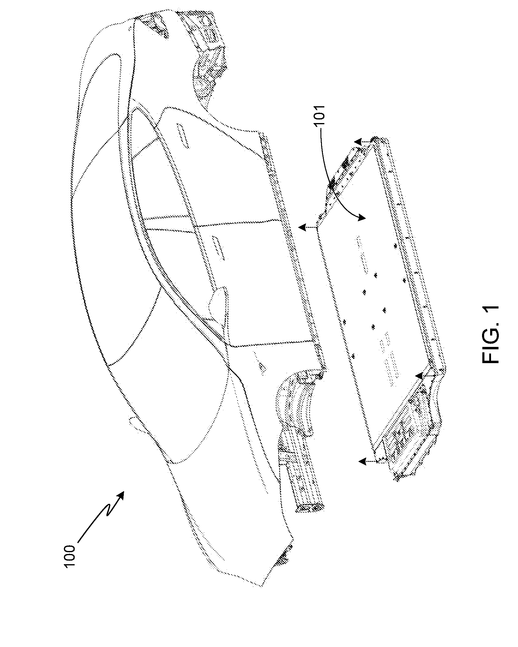
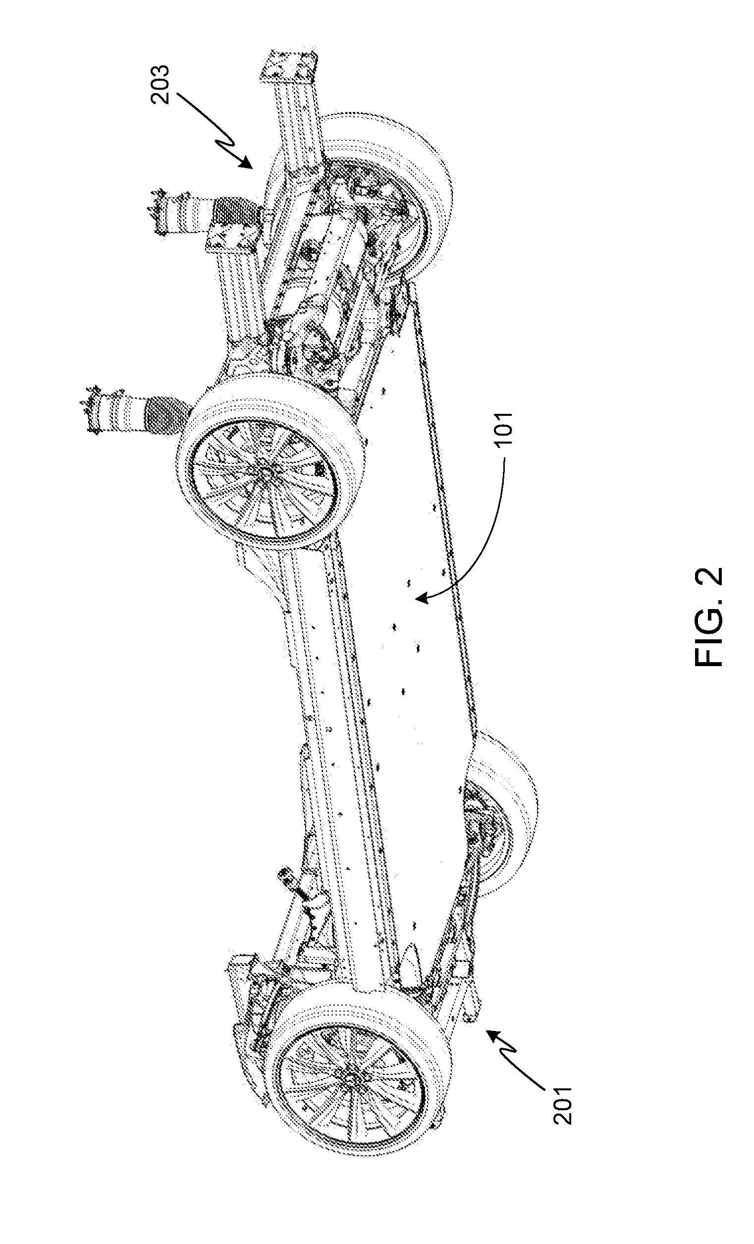
Battery Pack Base Plate Heat Exchanger

a heat exchanger and battery pack technology, applied in the field of vehicles, can solve the problems of increasing hydraulic losses, or pressure drop losses, affecting the efficiency and overall and affecting the performance of the inner heat exchanger. to achieve the effect of enhancing thermal energy withdrawal

Active Publication Date: 2014-07-10
TESLA INC
View PDF5 Cites 120 Cited by
  • Summary
  • Abstract
  • Description
  • Claims
  • Application Information

AI Technical Summary

Benefits of technology

[0015]The heat exchanger conduits may be attached to the inside surface of the battery enclosure base plate by brazing, soldering, welding or bonding. The heat exchanger conduits m...

Problems solved by technology

An increase in these same variables, however, also results in an increase in the hydraulic losses, or pressure drop losses, which are manifested in increased aerodynamic drag (i.e., vehicle motive power), pump power, and fan power.
A principal drawback of the practice of stacking heat exchangers is an increase in hydraulic losses (i.e., fan power, aerodynamic drag) that result regardless of whether each heat exchanger in the stack is in active use.
Additionally, since the temperature of the air entering the inner heat exchanger(s) will be the temperature of the air exiting the upstream heat exchanger wh...

Method used


Image

  • Battery Pack Base Plate Heat Exchanger
  • Battery Pack Base Plate Heat Exchanger
  • Battery Pack Base Plate Heat Exchanger

Examples


Embodiment Construction

[0037]In the following text, the terms “battery”, “cell”, and “battery cell” may be used interchangeably and may refer to any of a variety of different cell types, chemistries and configurations including, but not limited to, lithium ion (e.g., lithium iron phosphate, lithium cobalt oxide, other lithium metal oxides, etc.), lithium ion polymer, nickel metal hydride, nickel cadmium, nickel hydrogen, nickel zinc, silver zinc, or other battery type / configuration. The term “battery pack” as used herein refers to multiple individual batteries contained within a single piece or multi-piece housing, the individual batteries electrically interconnected to achieve the desired voltage and capacity for a particular application. The term “electric vehicle” as used herein refers to either an all-electric vehicle, also referred to as an EV, or a hybrid (HEV) / plug-in hybrid (PHEV) vehicle, where hybrid vehicles utilize multiple propulsion sources one of which is an electric drive system.

[0038]In a...


PUM


Abstract

A heat exchanger integrated into an electric vehicle's battery pack enclosure is provided, where the heat exchanger conduits are mechanically and thermally coupled to the inside surface of the enclosure base plate and where the battery pack enclosure is mounted such that ambient air flows over the outside surface of the enclosure base plate during vehicle motion. A thermal management system is coupled to, and controls operation of, the integrated battery pack heat exchanger such that in a first operational mode the heat exchanger is thermally coupled to the batteries within the battery pack, and in a second operational mode the heat exchanger is thermally decoupled from the batteries within the battery pack.

Description

FIELD OF THE INVENTION[0001]The present invention relates generally to vehicles and, more particularly, to an automotive heat exchanger.BACKGROUND OF THE INVENTION[0002]Vehicle cooling systems vary widely in complexity, depending primarily upon the thermal requirements of the various vehicle systems employed in the vehicle in question. In general, these cooling systems utilize heat exchangers of one form or another to transfer the heat generated by the vehicle subsystems to the surrounding ambient environment. Such heat transfer may either be performed directly, for example in the case of a simple radiator coupled to a vehicle engine, or indirectly, for example in the case of a thermal management system utilizing multiple heat transfer circuits to transfer the heat through multiple stages in order to sufficiently lower the temperature of the component in question.[0003]In general, vehicle heat exchangers are designed to exchange heat between two different fluids, or two similar flui...

Claims


Application Information

Patent Timeline
IPC IPC(8): H01M2/10B60L50/64
CPCH01M2/1016H01M10/625H01M10/6556H01M10/6562Y02E60/10B60K1/04B60K2001/0438B60K2001/005B60K11/02B60K11/04H01M50/249H01M10/658B60L50/64H01M50/213Y02T10/70
Inventor MARDALL, JOSEPHYEOMANS, PAUL
Owner TESLA INC
Why Eureka
Try Eureka