
Process for curing low-dielectric constant material

a technology curing process, which is applied in the direction of furnaces, furnace types, hearth type furnaces, etc., can solve the problems of low-dielectric constant performance relative dielectric constant, and deterioration of semiconductor substrates, so as to suppress the influence of heat from lamps and increase the mechanical strength of low-dielectric constant material. , the effect of increasing the mechanical strength of low-dielectric constan

Inactive Publication Date: 2014-07-17
USHIO DENKI KK
View PDF5 Cites 3 Cited by
  • Summary
  • Abstract
  • Description
  • Claims
  • Application Information

AI Technical Summary

Benefits of technology

The present invention provides a curing process for low-dielectric constant material on a semiconductor substrate using ultraviolet rays. This process improves the mechanical strength of the material while maintaining its low-dielectric constant performance, and suppresses overheating of the substrate caused by heat from the lamps. The use of a fluorescent lamp with specific wavelength range of ultraviolet rays reduces heat generation and allows for safer and effective curing of the low-dielectric constant material.

Problems solved by technology

However, when high-pressure mercury lamps are used as the ultraviolet light source, since the amount of heat generation associated with light emission of the high-pressure mercury lamps is large, the semiconductor substrate is not only heated by irradiation of the low-dielectric constant material film with the light from the high-pressure mercury lamps but also heated by the heat associated with light emission of the high-pressure mercury lamps.
This causes a problem in that the semiconductor substrate deteriorates due to overheating caused by the influence of the heat from the lamps during the curing processing on the low-dielectric constant material.
However, irradiation with the light from the xenon excimer lamps causes an increase in relative dielectric constant, and this causes a problem in that the low-dielectric constant performance of the low-dielectric constant material cannot be maintained.

Method used


Image

  • Process for curing low-dielectric constant material
  • Process for curing low-dielectric constant material
  • Process for curing low-dielectric constant material

Examples


experimental example 1

Curing Processing (1)

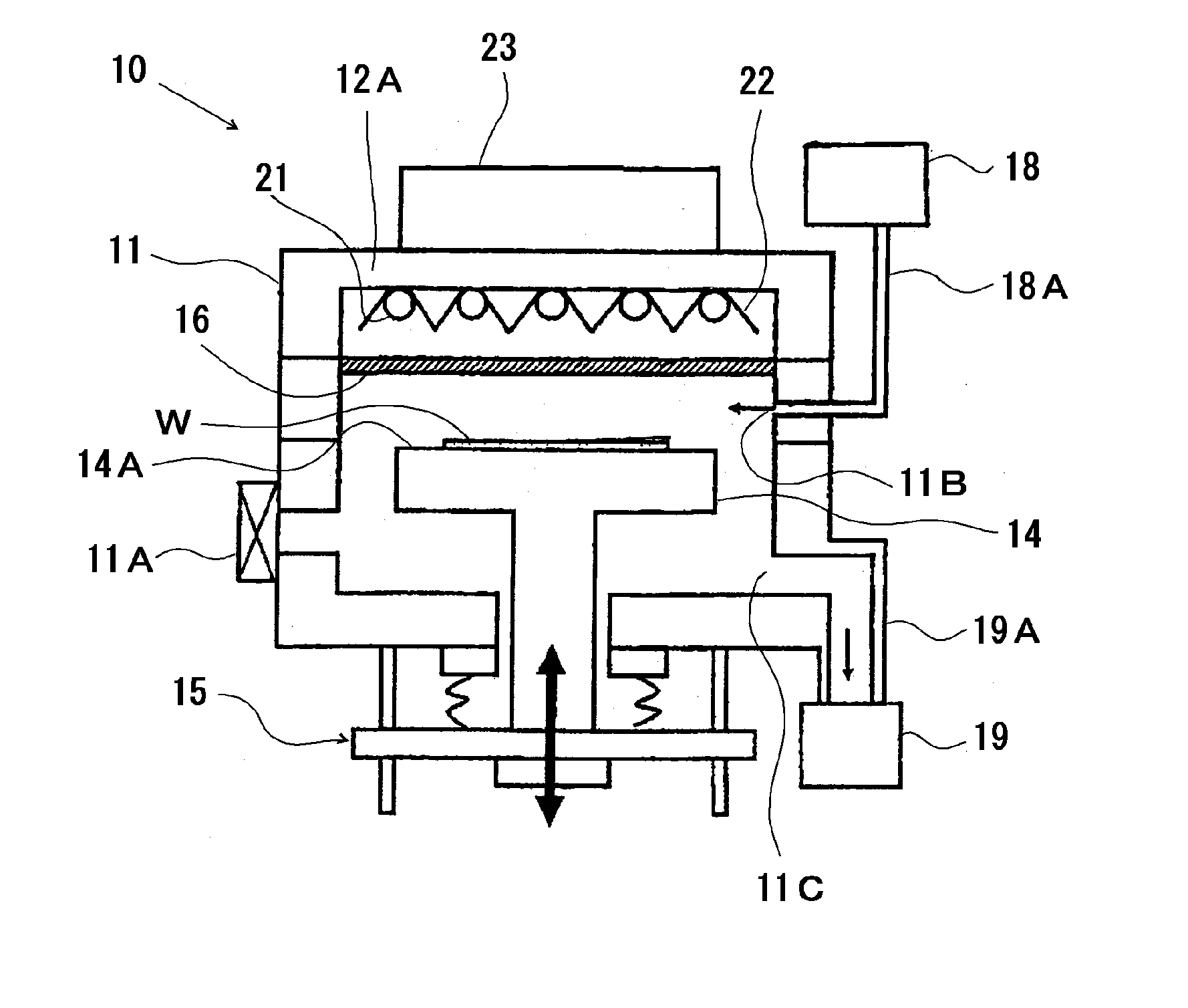
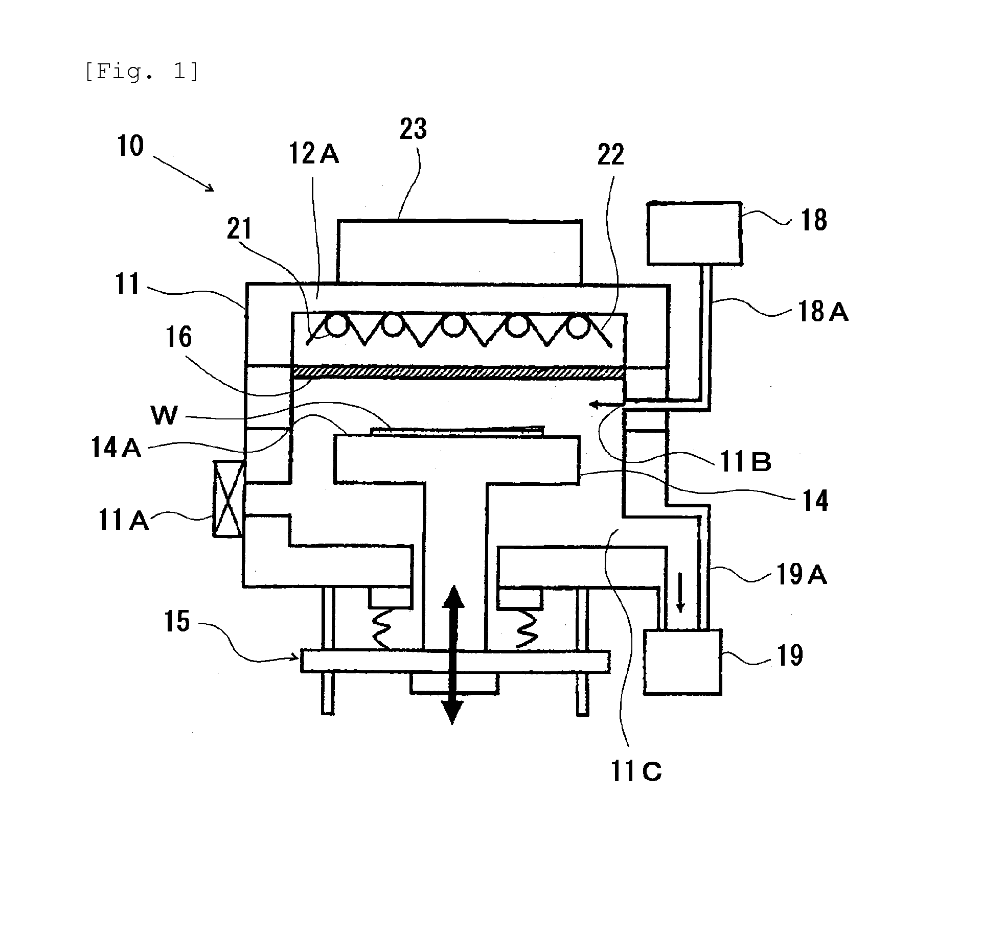
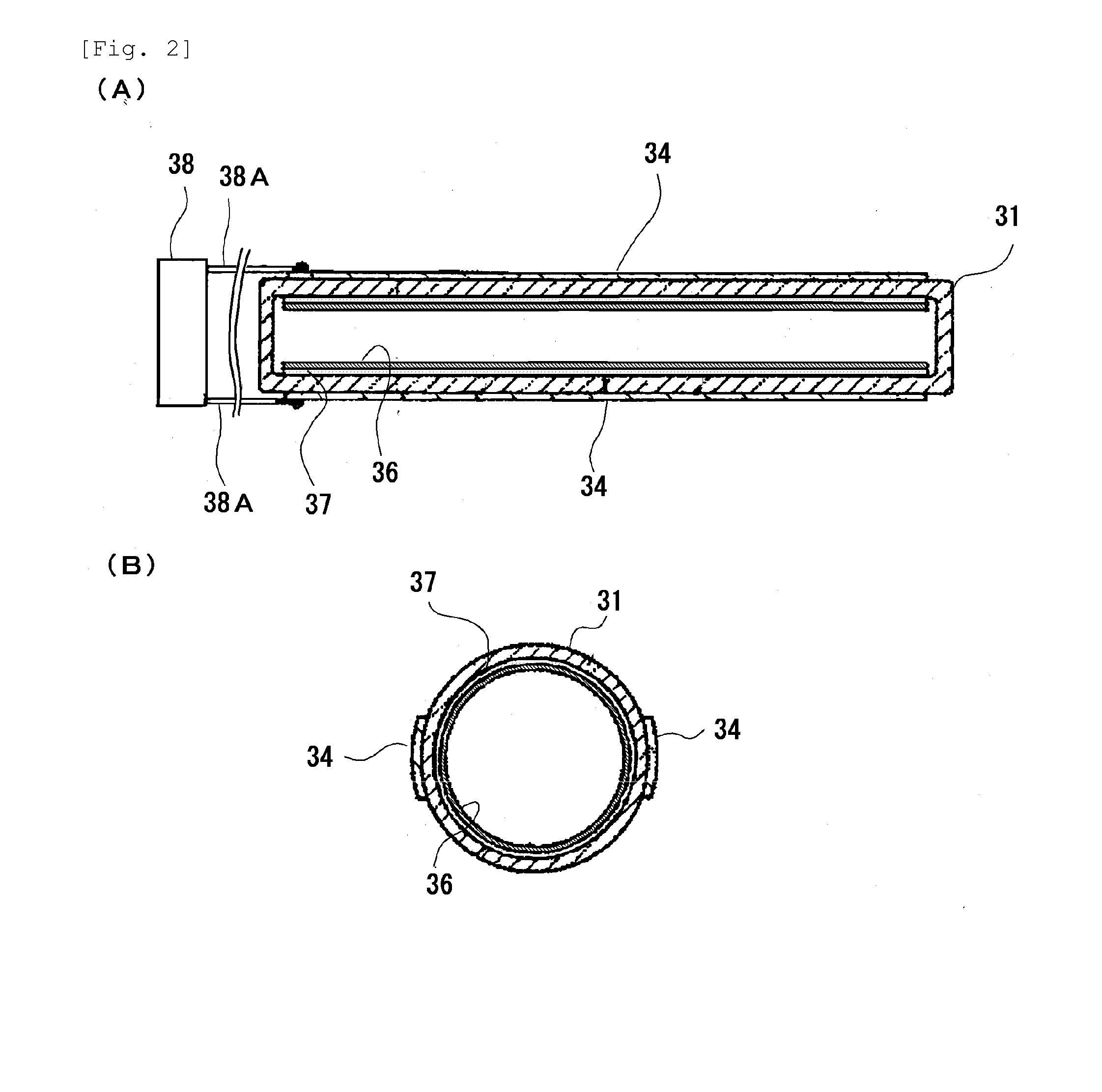
[0043]A curing apparatus having the configuration shown in FIG. 1 (the curing apparatus may be referred to as a “curing apparatus (1)”) was produced. In the curing apparatus (1), fluorescent lamps having the configuration shown in FIGS. 2A and 2B and each including a phosphor layer containing a phosphor composed of neodymium-activated yttrium phosphate (these fluorescent lamps may be referred to as “fluorescent lamps (1)”) were used as the ultraviolet light source. In each fluorescent lamp (1), xenon gas was used as the discharge gas, and the light-emitting tube (31) was made of quartz glass and had an outer diameter of 10 mm and an inner diameter of 9 mm. The fluorescent lamps (1) had an emission length of 400 mm, were turned on at an emission intensity of 7.2 mW / cm2, and emitted light with a spectral distribution shown in FIG. 5. The casing (11) used was made of anodized aluminum, and quartz glass was used for the irradiation window (16).

[0044]In the produced ...

experimental example 2

[0060]For each of the curing apparatus (1) to curing apparatus (4) and curing apparatus (7) produced in Experimental Example 1, the effective irradiation distance of the ultraviolet light source was measured. The results are shown in TABLE 2. One of the curing apparatus (1) to curing apparatus (4) and curing apparatus (7) was used, and then the position of the mounting table (14) having a processing target (W) mounted thereon was adjusted by the driving mechanism (15) such that the separation distance between the processing target (W) and the ultraviolet light source became the effective irradiation distance of the ultraviolet light source. Then the casing (11) was reduced in internal pressure such that the degree of vacuum was 5 Torr. Then the plurality of lamps in the ultraviolet irradiation unit were turned on simultaneously under the input power condition shown in TABLE 2 to irradiate the low-dielectric constant material film in the processing target (W) with ultraviolet rays fo...


PUM

PropertyMeasurementUnit
wavelengthaaaaaaaaaa
wavelengthsaaaaaaaaaa
peak wavelengthaaaaaaaaaa

Abstract

Provided is a low-dielectric constant material curing process including irradiating a low-dielectric constant material on a semiconductor substrate with ultraviolet rays. In the low-dielectric constant material curing process, the ultraviolet light source is a fluorescent lamp including: a light-emitting tube sealed and filled with a discharge gas containing xenon gas; a pair of electrodes for inducing a discharge in the interior space of the light-emitting tube; a dielectric material being interposed between the interior space and at least one of the pair of electrodes; and a phosphor layer formed on a surface of the light-emitting tube and containing a phosphor that is excited by light generated from the discharge gas by a discharge in the interior space. The phosphor emits ultraviolet rays having a wavelength within a range of 180 to 300 nm.

Description

TECHNICAL FIELD[0001]The present invention relates to a low-dielectric constant material curing process for curing a low-dielectric constant material by irradiating the low-dielectric constant material on a semiconductor substrate with ultraviolet rays.BACKGROUND ART[0002]In recent semiconductor devices, interlayer dielectrics formed from low-dielectric constant materials are used. Such an interlayer dielectric is produced by a process including forming a low-dielectric constant material film on a semiconductor substrate and curing the obtained low-dielectric constant material film by irradiation with ultraviolet rays. Such curing processing by irradiation of the low-dielectric constant material with ultraviolet rays can improve its mechanical strength. High-pressure mercury lamps or xenon excimer lamps are used as the ultraviolet light source for irradiating the low-dielectric constant material on the semiconductor substrate with ultraviolet rays (see, for example, Japanese Patent ...

Claims


Application Information

Patent Timeline
Patent Type & Authority Applications(United States)
IPC IPC(8): F26B3/28
CPCF26B3/28
Inventor WASAMOTO, MAKOTOHABU, TOMOYUKIYABU, SHINTARO
Owner USHIO DENKI KK
Learn More