Glass substrate with sealing material layer, organic el device using same, and manufacturing method for electronic device

a technology of sealing material and glass substrate, which is applied in the direction of glass tempering apparatus, glass reforming apparatus, special ornamental structures, etc., can solve the problems of degrading the display characteristic of the oled display time-dependently, the inability of the organic resin-based bonding material to completely block the gas penetration, and the inability to maintain the air tightness inside the oled display

Active Publication Date: 2014-07-17
NIPPON ELECTRIC GLASS CO LTD
View PDF5 Cites 34 Cited by
  • Summary
  • Abstract
  • Description
  • Claims
  • Application Information

AI Technical Summary

Benefits of technology

[0113]Sixteenth, in the glass substrate with a sealing material layer according to the third related invention, the content of the refractory filler preferably gradually decreases from the surface region of the sealing material layer toward the internal region thereof.

Problems solved by technology

However, the organic resin-based bonding material cannot block penetration of gas completely.
Thus, when the organic resin-based bonding material is used, air tightness inside the OLED display cannot be maintained.
Owing to this, an organic light-emitting layer, which has low water resistance, is liable to degrade, resulting in such a failure that a display characteristic of the OLED display degrades time-dependently.
Hence, when the OLED display is used over a long period, reliability of the display is liable to deteriorate.
However, the glass powder generally has a softening point of 300° C. or more, and hence it has been difficult to apply the glass powder to the OLED display.
However, an active element used in an OLED display only has heat resistance to a temperature of about 120 to 130° C., and hence, when glass substrates are sealed with each other by this method, the active element is damaged by heat, resulting in degradation of a display characteristic of the OLED display.
In addition, an organic light-emitting material is also poor in heat resistance, and hence, when glass substrates are sealed with each other by this method, the organic light-emitting material is damaged by heat, resulting in degradation of a display characteristic of the OLED display.

Method used


Image

  • Glass substrate with sealing material layer, organic el device using same, and manufacturing method for electronic device
  • Glass substrate with sealing material layer, organic el device using same, and manufacturing method for electronic device
  • Glass substrate with sealing material layer, organic el device using same, and manufacturing method for electronic device

Examples


embodiment of first invention

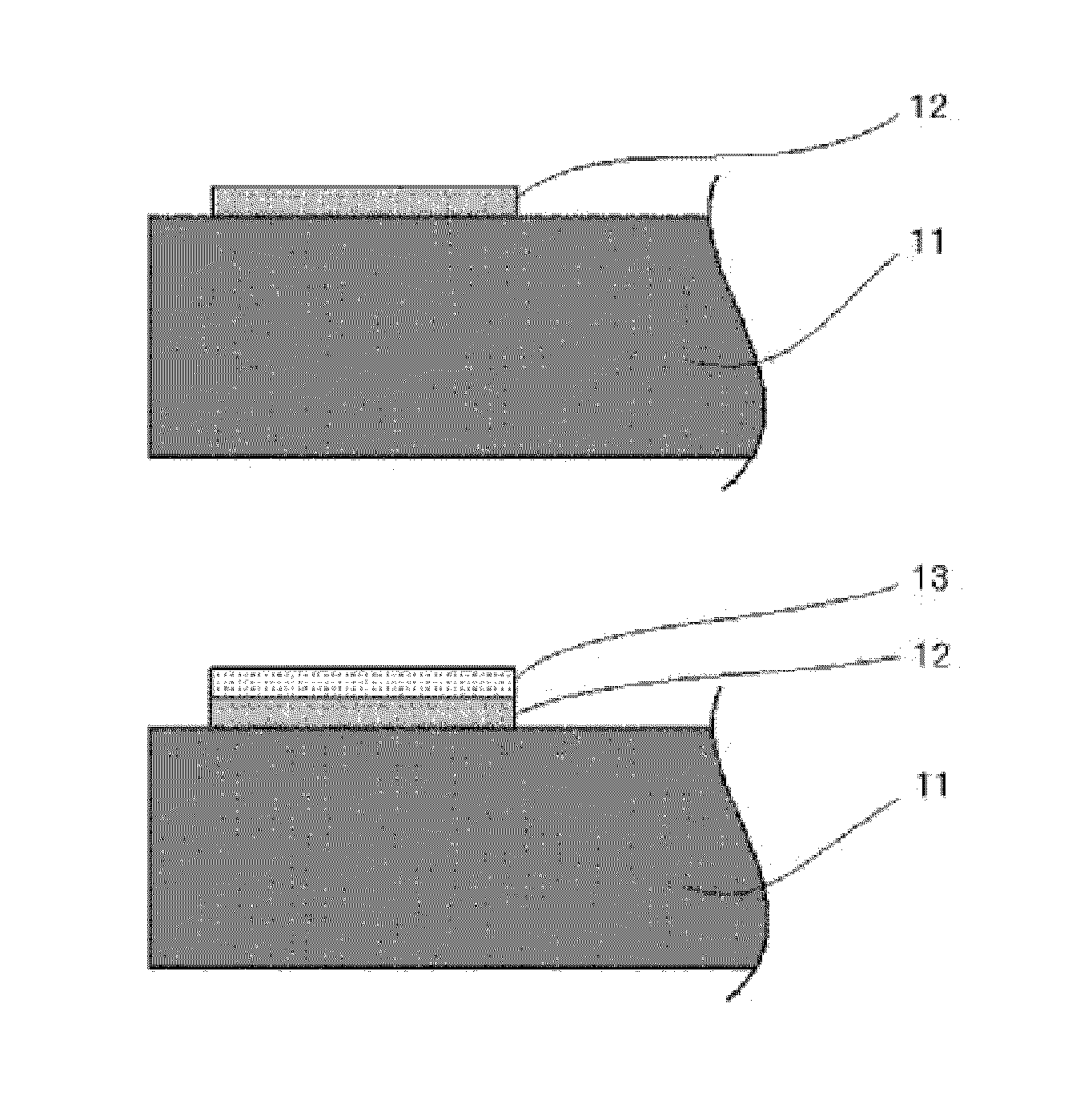
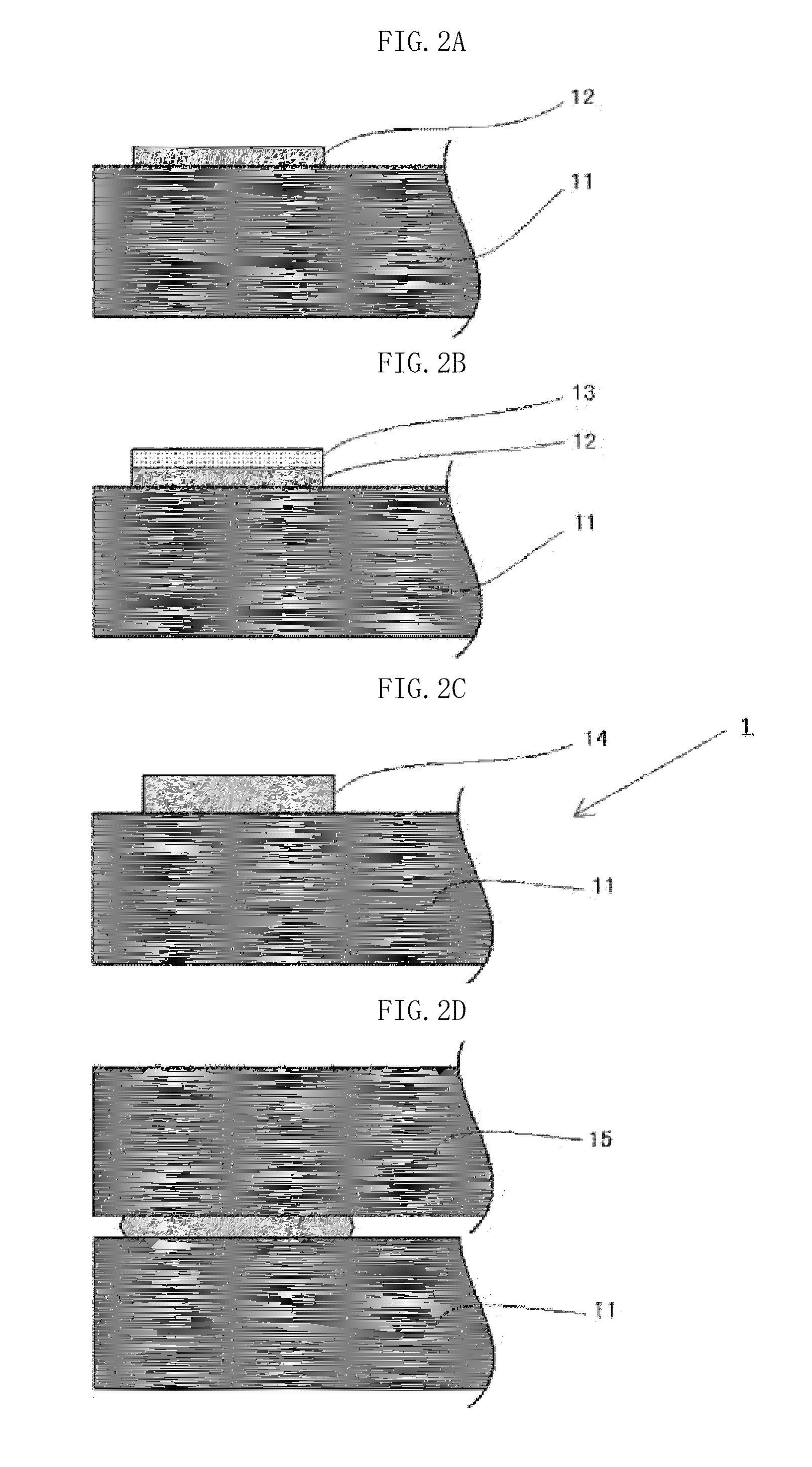
[0119]A glass substrate with a sealing material layer according to an embodiment of the first invention has a sealing material layer formed by firing a sealing material. The sealing material comprises inorganic powder comprising glass powder and a refractory filler. As the sealing material comprises a refractory film, the thermal expansion coefficient of the sealing material layer can be reduced and the mechanical strength of the sealing material layer can be enhanced. The suitable formulations of the glass powder and refractory filler are as mentioned below.

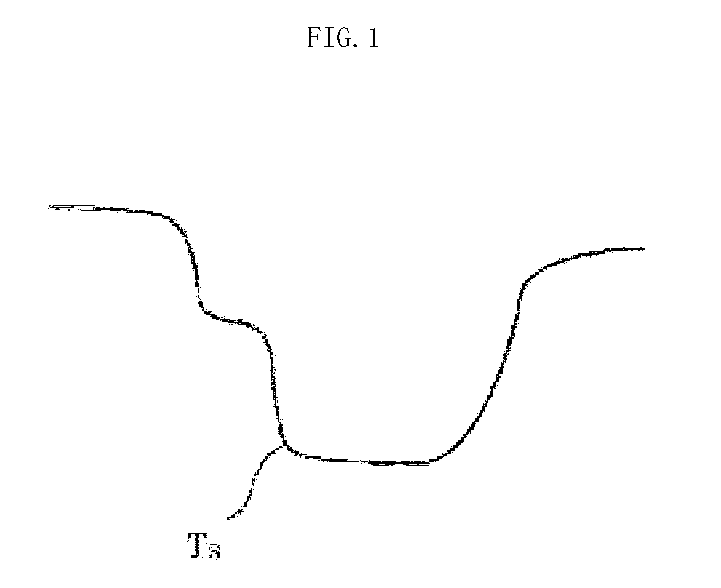
[0120]The glass powder is preferably SnO-containing glass powder. The SnO-containing glass powder preferably comprises, as a glass composition expressed in mol % in terms of the following oxides, 35 to 70% of SnO and 10 to 30% of P2O5. The reasons why the range of the glass composition has been limited as described above are shown below. It should be noted that, in the following description of the range of the glass composition,...

embodiment of second invention

[0192]A method of producing an electronic device according to an embodiment of the second invention comprises the steps of: (1) preparing a glass substrate; (2) mixing a sealing material comprising glass powder and a vehicle comprising an organic binder to manufacture a sealing material paste; (3) applying the sealing material paste onto the glass substrate to form a coating layer; (4) firing the coating layer to yield a glass substrate with a sealing material layer; (5) laminating, via the sealing material layer, the glass substrate with a sealing material layer and a glass substrate without a sealing material layer; and (6) irradiating the laminate with laser light so that a laser sealing temperature is equal to or lower than a firing temperature to hermetically seal the glass substrate with a sealing material layer and the glass substrate without a sealing material layer.

[0193]In the step (2), a mixing method using a kneading apparatus such as a roll mill, a beads mill, or a ball...

example 1

[0490]Examples of the first invention are described. It should be noted that the following examples are merely for illustrative purposes. The first invention is not limited to the following examples at all.

[0491]Table 1 shows each SnO-containing glass powder (Sample Nos. 1 to 7). Further, Table 2 shows each Bi2O3-containing glass powder (Sample Nos. 8 to 14).

TABLE 1No. 1 No. 2 No. 3No. 4No. 5No. 6No. 7(mol %)SnO59646455505655.1P2O520252421233227ZnO5431010813B2O3154710120.9Al2O311234Li2O1122K2O1122Melting950900900950950900900temperature (° C.)Glass transition320295307323334305310point (° C.)Softening point392364376390405378383(° C.)Thermal10612511810296120113expansioncoefficient(×10−7 / ° C.)

TABLE 2No. No. No.No.No.No.No.891011121314(mol %)Bi2O337373742424242B2O326262624242424ZnO17.51418152124.519.5BaO51013.58510CuO1412510124.53Fe2O30.510.510.51Al2O30.50.5Melting1,1001,1001,1001,0001,0001,0001,000temperature (° C.)Glass 365362364350351352355transitionpoint (° C.)Softening 4354334354194...


PUM

PropertyMeasurementUnit
surface roughnessaaaaaaaaaa
surface roughness RMSaaaaaaaaaa
thicknessaaaaaaaaaa

Abstract

Provided is a glass substrate with a sealing material layer, including a sealing material layer formed by sintering a sealing material, in which: the sealing material includes at least inorganic powder; the inorganic powder includes glass powder and a refractory filler; the content of refractory filler in the inorganic powder is 10 to 35 vol %; and the sealing material layer has a surface roughness Ra of less than 0.5 μm.

Description

TECHNICAL FIELD[0001]The present invention relates to a glass substrate with a sealing material layer and an OLED device using the same, and more specifically, to a glass substrate with a sealing material layer suitable for sealing treatment with a laser (hereinafter referred to as laser sealing) and an OLED device using the same. The present invention also relates to a method of producing an electronic device, and more particularly, to a method of producing an OLED device by laser sealing.BACKGROUND ART[0002]In recent years, an OLED display has been attracting attention as a flat display panel. The OLED display can be driven by a DC voltage, and hence its drive circuit can be simplified. In addition, the OLED display has advantages such as having no viewing angle dependence unlike a liquid crystal display, being bright due to its self-luminescence, and having a rapid response speed. At present, the OLED display is mainly used in a small portable appliance such as a mobile phone, an...

Claims


Application Information

Patent Timeline
Patent Type & Authority Applications(United States)
IPC IPC(8): C03B23/24H05B33/04C03C8/24C03C17/04
CPCC03B23/245C03C8/24H05B33/04C03C17/04C03C3/14C03C3/19C03C8/04C03C8/08C03C27/10B32B17/06C03C17/008Y10T428/24421Y10T428/24413H10K50/8426H10K71/00
Inventor MASUDA, NORIAKISHIRAGAMI, TORUARAKAWA, HIROSHI
Owner NIPPON ELECTRIC GLASS CO LTD
Why Eureka
Try Eureka