
A Combustion System

a combustion system and combustion technology, applied in the field of combustion systems, can solve the problems of inefficient combustion of biomass fuel, high cost, and high cost, and achieve the effect of increasing the flame path and increasing the time available to fully burn

Active Publication Date: 2014-07-17
STEWART JASON JOREN JENS
View PDF2 Cites 6 Cited by
  • Summary
  • Abstract
  • Description
  • Claims
  • Application Information

AI Technical Summary

Benefits of technology

The invention is a fireplace design that improves the combustion process in a wood burner. By extending the flue towards the fire base, the combustion gases are required to travel down and across the charcoal / reduction layer, resulting in a higher reduction of volatiles and steam to combustible gases. This increases the heating process and allows for a longer flame path. The insulation means also helps to introduce air turbulence and mixing, enhancing the combustion process. Overall, the design improves the efficiency and effectiveness of the fireplace.

Problems solved by technology

A problem associated with the burning of biomass fuel in general is the production of air pollutants.
For example, the burning of biomass fuel (and particularly the inefficient burning of biomass fuel) may produce volatile, toxic, or other undesirable gases.
Furthermore, large amounts of smoke and particulate matter may also be released into the atmosphere.
In this regard open fireplaces are particularly inefficient.
That is, open fireplaces usually produce larger amounts of air pollutants, as compared to enclosed fireplaces.
Furthermore, an open fireplace generally only provides heat directly in front of the fireplace, with the vast majority of the heat being lost up through the chimney or out through the rear wall of the fireplace.
However, whilst the problems of the inefficient burning of biomass fuel for space heating can be addressed somewhat with a furnace, the extra capital cost is not always necessary, practical, or affordable.
Furthermore, furnaces tend to be used mainly in very cold climates, but not in temperate climates, and are also usually coupled to some sort of central heating, which is not always desirable.
Moreover, a further issue with furnaces is that they are usually completely closed off from view, and do not therefore provide the psychological or aesthetic benefits that are derived from lazy flame as a light source.
As yet, there does not appear to be a wood burner or fireplace designed for space heating that adequately incorporates the various stages of combustion in relation to each other.
However, most wood burners lack the ability to burn or convert such gases (and their precursors such as carbon dioxide and water) due to the wood burner not being able to produce enough heat to do so (conventional wood burners usually reach maximum temperatures of between 600° C.-800° C.).
Hence, attaining a high enough temperature during secondary combustion to consume all the volatiles distilled during pyrolysis or combustion is difficult because the necessary temperature is often higher than that which can ordinarily be generated.
Hence, a disadvantage associated with Craver is that the design of the wood burner does not attain high enough temperatures to adequately consume the vast majority of gases or particulate matter.
Furthermore, the wood burner described in Craver is not able to be retro-fitted to an existing wood burner or other fireplace.
However, these Regulations are not retrospective, and hence they only have effect in relation to wood burners manufactured and sold after the Regulations came into force.
Moreover, to date there have been no innovations which have enabled people to bring their older wood burners up to modern compliance levels (voluntarily or otherwise).
Refueling causes quenching, a situation where the introduction of fresh fuel to the fire is not supported by the heat contained within the existing fire to adequately pyrolyse the biomass.
However, the reduction in available oxygen and the corresponding detrimental effect on combustion results in more air pollutants being produced and released.
Because this often results in the amount of air pollutants exceeding the minimum regulated amounts, many modern wood burner designs have denied the user the ability to shut down the air supply.
The air supply also affects the dynamics of wood burners because a greater draught causes more heat to be generated, but a greater portion of heat is lost up the flue.
The higher velocity of gases also results in more particulate matter being exhausted to the atmosphere.
Conversely, a lesser draught reduces the amount of particulate matter being drawn from the combustion chamber but also reduces the heat output.
Or to put it another way, greater air means greater heat, but lower efficiency, however the greater heat actually results in a cleaner burn which lowers the emissions.
However, catalytic converters are generally very expensive, and may be considered complex to operate and / or understand by many people—and this may be prohibitive to both wood burner manufacturers and end consumers.
Furthermore, the installation of catalytic converters requires specialist knowledge and significant alterations to be made to the wood burner, and flue, and this can be time consuming, complex and expensive.

Method used


Image

  • A Combustion System
  • A Combustion System
  • A Combustion System

Examples


Embodiment Construction

[0087]The description of a preferred form of the invention to be provided herein, with reference to the accompanying drawings, is given purely by way of example and is not to be taken in any way as limiting the scope or extent of the invention.

DRAWINGS

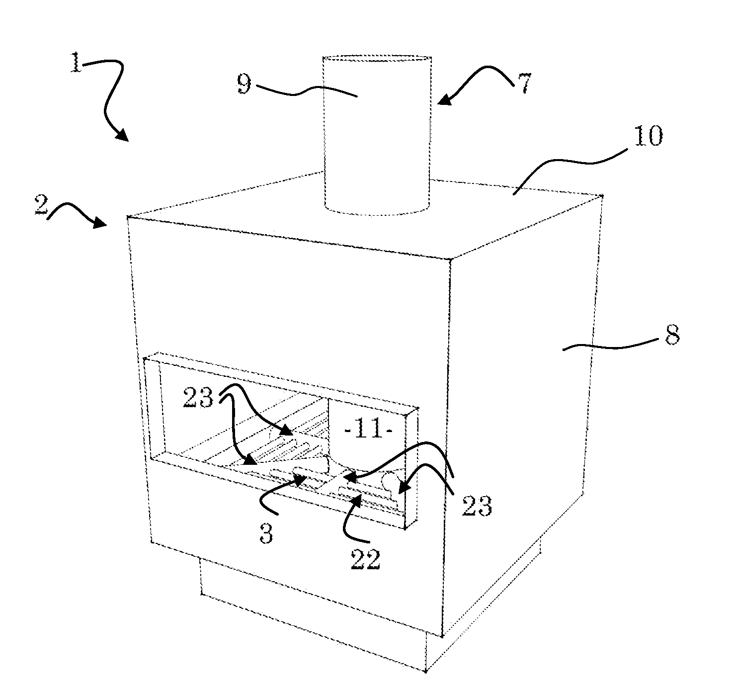
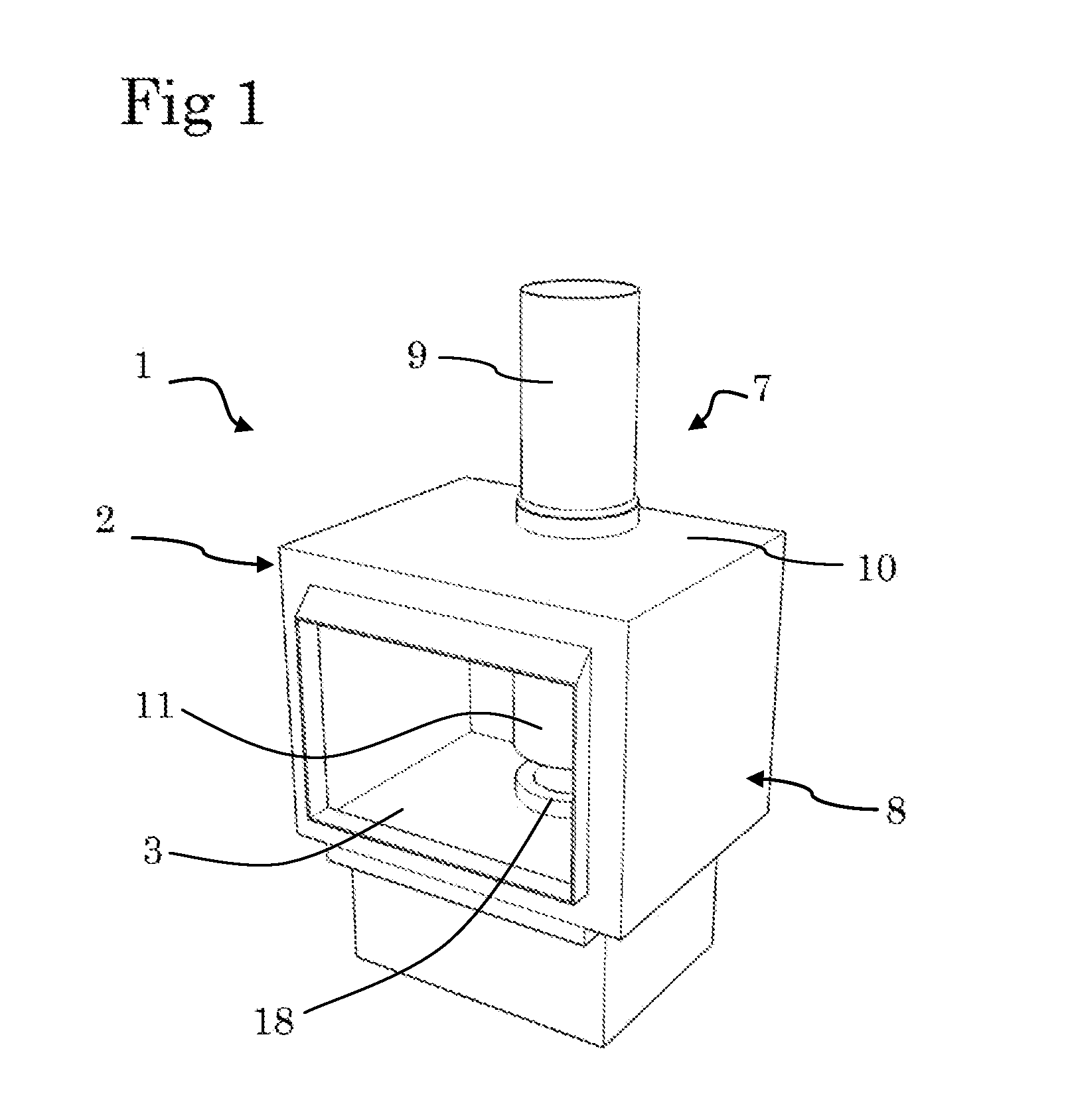
[0088]FIG. 1: is a perspective front view of a wood burner which incorporates one possible embodiment of the present invention,

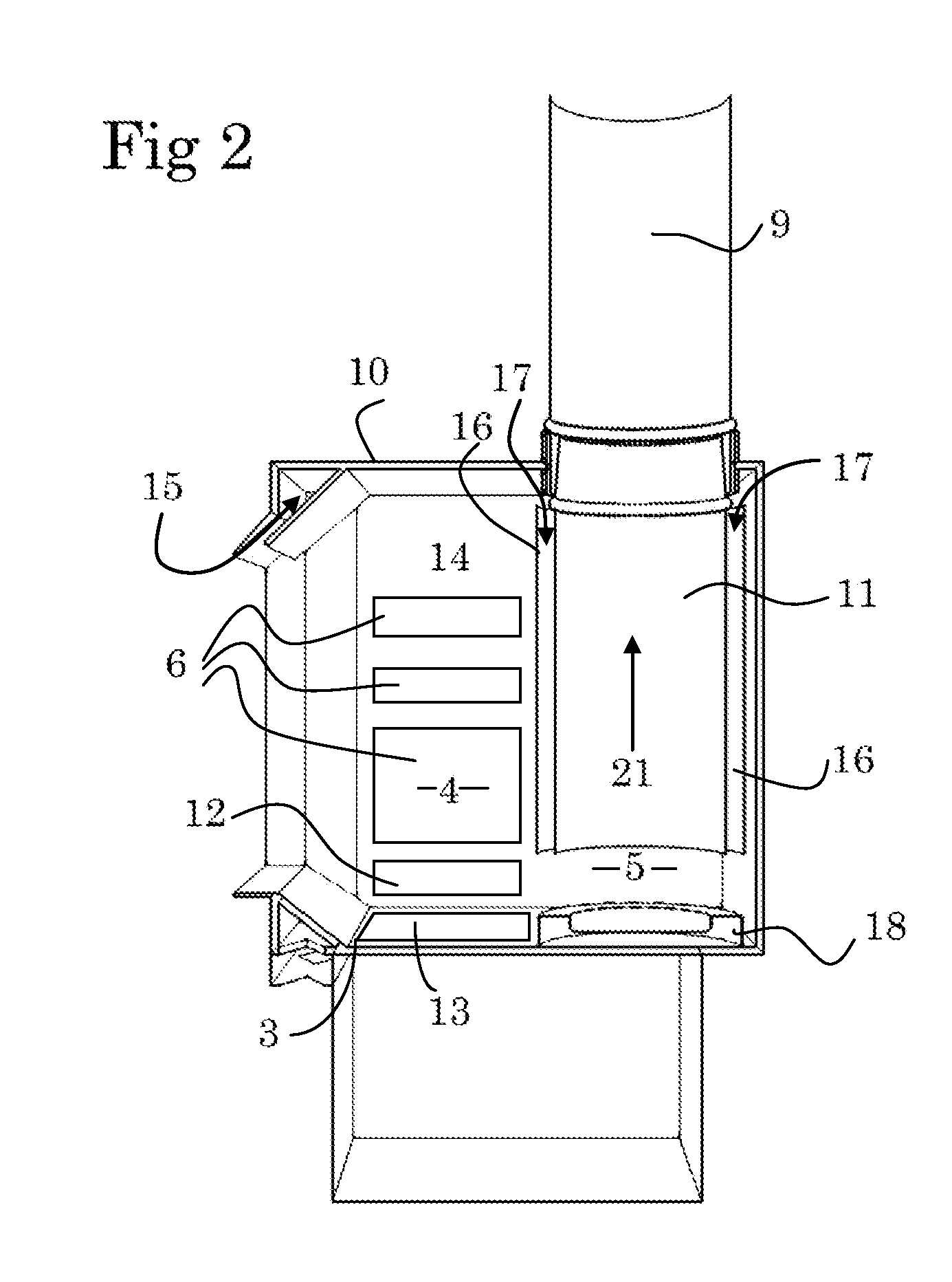
[0089]FIG. 2: is a cut-away side view of the embodiment illustrated in FIG. 1,

[0090]FIG. 3: is a cut-away side perspective view of another possible embodiment of the present invention,

[0091]FIG. 4: is a perspective front view of yet another possible embodiment of the present invention, and

[0092]FIG. 5: is a cut-away side view of the embodiment illustrated in FIG. 4.

DESCRIPTION OF PREFERRED EMBODIMENTS

[0093]Having regard to FIGS. 1 and 2 there is shown a combustion system generally indicated by arrow 1.

[0094]The combustion system 1 includes a fireplace in the form of a wood burner 2.

[0095]The wood burner 2 inclu...


PUM


Abstract

This invention relates to a combustion system. The combustion system includes a fireplace which has a fire base, a primary combustion zone for pyrolysising and / or combusting a biomass fuel, and a secondary combustion zone for combusting gases and / or particulate matter produced from the pyrolysis and / or combustion of the biomass fuel. The combustion system also includes an exhaust flue, the exhaust flue extending to a position near to, or adjacent, the secondary combustion zone and / or the fire base. The invention may be particularly suitable for use in relation to wood burners, either by retrofitting to existing wood burners or by incorporating into new wood burners.

Description

FIELD[0001]This invention relates to a combustion system for use in the combustion of biomass fuels such as wood. The invention may be particularly suitable for use in relation to domestic wood burners, and for convenience only therefore, the invention will be predominantly described in relation to such use.[0002]However, it is to be understood and appreciated that the invention may also have other applications and / or uses—for example, in relation to open fireplaces, masonry fireplaces, and furnaces. The combustion system may also have industrial applications or uses.[0003]The prior art and possible applications of the invention, as discussed below, are therefore given by way of example only.BACKGROUND[0004]A problem associated with the burning of biomass fuel in general is the production of air pollutants. For example, the burning of biomass fuel (and particularly the inefficient burning of biomass fuel) may produce volatile, toxic, or other undesirable gases. Furthermore, large am...

Claims


Application Information

Patent Timeline
IPC IPC(8): F24B1/02F23L9/02F23L1/02F23L15/04F23G5/027F23G5/04
CPCF24B1/026F24B1/028F23G5/0276F23L9/02F23L1/02F23L15/04F23G5/04F23B60/00F23B90/04Y02E20/34
Inventor STEWART, JASON JOREN JENS
Owner STEWART JASON JOREN JENS
Learn More