Digital printing and embossing

Inactive Publication Date: 2014-07-17
CERALOC INNOVATION AB
View PDF16 Cites 37 Cited by
  • Summary
  • Abstract
  • Description
  • Claims
  • Application Information

AI Technical Summary

Benefits of technology

[0075]Thermal printing with heating print heads are also used to create digital prints directly on a heat sensitive paper or indirectly with a thermal transfer printing method where the heat is applied on a heat sensitive transfer film. These printing methods are mainly used to apply one colour on a paper and to print for example labels. The heating print heads have several advantages. They are reliable since there are no risks for clogging of inks and the price is cost competitive. The major disadvantages are related to high cost for the paper or transfer film and the colour limitations to mainly one colour. Heating print heads are available in widths of up to 200 mm and may provide a resolution of up to 600 DPI.
[0076]Digital printing is a very flexible method that may provide a high quality print but

Problems solved by technology

The disadvantage is that they are less transparent and the decorative pattern is covered by a grey layer that disturbs the printed pattern.
The production process is rather complicated and is only cost efficient in very large production volumes.
It is more difficult to create designs such as for example wood decors.
The penetration is however rather limited since the ink drops will be bonded to the first particle that they hit, mainly the wood fibres.
Additional circumstances that that have contribute to the introduction of the digital printing technology in the tile industry is the fact that ceramic tiles are rather small compared to for example laminate and powder based floors that are produced as large pressed boards of about 2.1*2.7 m. Rather small printers with limited number of print heads may be used in the tile industry and the initial investment is rather limited.
However the volumes are still very small, especially in wood and laminate flooring applications, mainly due to high cost of the ink and high investment cost for the industrial printers.
The flexibility that the digital printing technology provides is limited by the embossing that is fixed and not possible to adapt to the variations of the digitally printed décor.
Such printers are slow but one small print head can generate a bigger image.
However a part print is not as flexible as a full print since the base colours are more difficult to change than when a full print is used.
Thermal technology imposes the limitation that the ink must be heat-resistant, generally up to 300° C. because the firing process is heat-based.
This makes it very difficult to produce pigment based multi colour thermal heads.
A main problem for all types of inks and print heads is that when ink dries by evaporation it may dry up and clog the nozzles.
This is difficult particularly at the rather low viscosities, which are required for a good functioning of the print heads.
Pigments have a natural tendency to settle out and fall down in the liquid carrier.
The inclusion of resins that serve as binder in the ink composition limits the possible amount of pigments, as both components increases the ink viscosity.
Colour pigments as raw

Method used


Image

  • Digital printing and embossing
  • Digital printing and embossing
  • Digital printing and embossing

Examples


Example

Example 1

Dry Ink Comprising Spray Dried Melamine

[0303]Dry ink powder was produced by mixing 50% (weight) spray dried melamine particles (Dynea 4865) having an average size of about 100 microns and 50% black colour pigments (Printex). The mixing was made in 80% humidity. The mix was thereafter dried in 30% humidity such that the pigments were bonded to the melamine particles. The melamine particles coated by pigments were sieved with a 150 micron net to remove oversized particles. A 50 microns net was thereafter used to remove undersized particles. Black dry ink powder comprising macro colourants with a particle size of about 50-150 microns was obtained.

Example

Example 2

Dry Fibre Based Ink

[0304]Dry ink powder was produced by mixing 20% (weight) spray dried melamine particles, 20% brown colour pigments and 60% wood fibres of pine with an average length of about 0.2 mm and a thickens of about 0.05 mm. The mix was applied as 1 mm thick layer by scattering equipment on a steal belt. The powder mix was thereafter heated and moisture was applied by steam from deionized water. The mix was dried by hot air such that a hard stabilized powder based surface layer was obtained with a semi cured melamine binder. The dried layer was removed from the belt by scraping and the dry particles were milled and sieved into dry ink colourants comprising a wood fibre body with a surface covered by pigments bonded to the surface of the fibres by the semi cured melamine resin.

Example

Example 3

Digital Binder and Powder Print

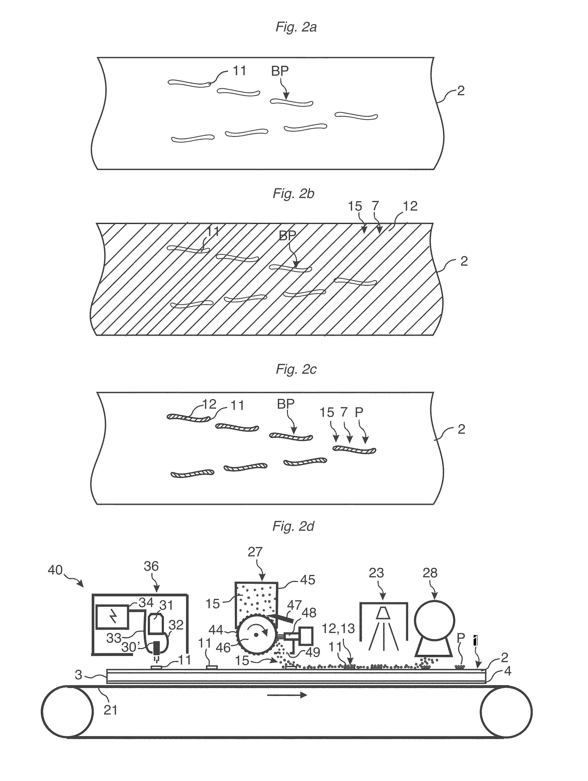
[0305]A powder mix of 300 g / m2 comprising wood fibres, melamine particles, brown colour pigments and aluminium particles was applied by scattering equipment on an 8 mm HDF core. The mix was sprayed with deionized water and dried by IR light such that a hard stabilized powder based surface with a brown basic colour was obtained. The panel with the stabilized powder surface was put on a conveyer and displaced under a digital Piezo print head. The digital print head applied drops of blank ink comprising mainly water on the stabilized surface and printed a transparent liquid wood grain pattern on the basic brown colour surface. The melamine under the transparent pattern melted when the digital coating Piezo head applied the water drops. Dry ink comprising spray dried melamine particles coated with pigments, as described in example one, was in a second step scattered over the whole surface and the transparent pattern. The panel was thereafter displ...


PUM

PropertyMeasurementUnit
Lengthaaaaaaaaaa
Structureaaaaaaaaaa
Thermosettingaaaaaaaaaa

Abstract

A method and equipment to form a digital print by applying dry colourants on a surface, bonding a part of the colourants with a binder and removing the non-bonded colourants from the surface. Also, a method to form embossed structures. Hard press particles may be applied in patterns on a carrier that is pressed against a surface.

Description

CROSS REFERENCE TO RELATED APPLICATIONS[0001]The present application claims the benefit of U.S. Provisional Application No. 61 / 751,418, filed on Jan. 11, 2013. The entire contents of U.S. Provisional Application No. 61 / 751,418 are hereby incorporated herein by reference in their entirety.TECHNICAL FIELD[0002]The disclosure generally relates to the field of digitally created decorative surfaces for building panels such as floor and wall panels. The disclosure relates to powder based colourants and hard particles that may be used to create decors and structures on such surfaces.FIELD OF APPLICATION[0003]Embodiments of the present invention are particularly suitable for use in floors, which are formed of floor panels comprising a core or a body, a decorative layer and preferably a transparent wear resistant structured layer above the decorative layer. Preferred embodiments are conventional laminate floors, powder based floor, wood floors, plastic based LVT floors and ceramic tiles. The...

Claims


Application Information

Patent Timeline
IPC IPC(8): B05D3/06B05D3/00
CPCB05D3/002B05D3/065B41J3/407B44C1/24B44C5/04B05D5/02B05D7/06B05D1/12B05D2401/32Y10T428/24901Y10T428/24066B05D1/36C09D11/103B05D3/067E04F15/02B41J2/0057B41J11/007B41J11/0024B41J11/00216C09J161/28C08L97/02C09D11/38B41M5/0017B41M7/00C08K3/013C08L61/28C08K3/22B41M5/0041B41M5/0076B05D5/06B41M5/00B41M3/00B41M5/0029B41M5/506B41M5/0023B05D1/02B41F19/002B41M5/502B41J3/28C09D7/69B05D3/12B05D7/50B05D7/52B05D7/53B32B27/14C08K2003/2227C09D11/037C09D161/28B41M1/22B41J3/54B41J2/005B41F19/007B41M1/38B32B21/02B32B29/002B32B3/30B32B3/06B32B2255/12B32B2307/4023B32B2607/00B32B2262/067B41J11/002B41F17/00B41J2/32B41J2/325B41M5/50B41J11/0015C09D197/02B41F19/02C09D11/02B41J2/14088B41J2/01
Inventor PERVAN, DARKOPERVAN, TONY
Owner CERALOC INNOVATION AB
Why Eureka
Try Eureka