Alignment, Verification, and Optimization of High Power Wireless Charging Systems

a wireless charging and wireless charging technology, applied in charging stations, electric vehicle charging technology, transportation and packaging, etc., can solve problems such as electric shock, cycle life, and high voltage cables, and achieve seamless and convenient parking procedures for the vehicle operator, and high complexity. , the effect of high level of complexity

Active Publication Date: 2014-08-07
WIRELESS CHARGE
View PDF14 Cites 139 Cited by
  • Summary
  • Abstract
  • Description
  • Claims
  • Application Information

AI Technical Summary

Benefits of technology

[0016]The invention is intended to address the problems with electric vehicle charging stations and anticipates that the parts of such systems will have to be verified and optimized before and after installation. Because no standard exists among manufacturers for the position of the secondary coil on the vehicle, the charging apparatus must be designed to be make and model independent. The use of a circular secondary coil on the bottom of the vehicle makes it accessible to a charging system regardless of vehicle size or how it is parked into position. In some known, above-ground, charging stations installed at the front of a parking space, a hard stop at the front wheels is required so that the vehicle does not collide with the charging unit. Since not all vehicles have the same distance from the front wheels to the bumper, generalizing such a design would appear to be impractical. In addition, any armature system would appear to require a high level of complexity and concomitant expense, since a movable armature would need to be actuated in multiple directions and extended outward against, the force of gravity as a cantilever. One object of the invention is to provide an alignment, apparatus that eliminates these problems.
[0017]Another object of the invention is to preserve the form of the parking spaces so that minimal changes to the existing parking infrastructure are necessary and that special maintenance of the infrastructure is riot required. A below ground or ground-level system allows for pull-though parking spaces in large open parking lots. Below ground systems also cannot be knocked into or damaged by vehicles, and they allow for easy outdoor maintenance such as snow removal.
[0018]Another object of the invention is to make the parking procedure seamless and easy for the vehicle operator and as close to parking a traditional internal combustion vehicle as possible.

Problems solved by technology

One disadvantage of this approach is that it requires the use of high voltage cables.
Frayed or damaged cables create a hazardous condition and can cause an electric shock.
Because the cable is repeatedly inserted and removed from a receptacle, cycle life is an issue.
Maintenance of public charging stations is another concern, especially in winter climates where reliability and accessibility could become issues in icy and snowy weather.
A plug-in system is also inconvenient as the vehicle operator must plug and unplug the charging unit from the vehicle.
Some disadvantages of inductive charging are its lower efficiency and increased resistive heating in comparison to plug-in systems.
Inductive charging also requires drive electronics and coils, increasing the complexity and cost of manufacturing.
However, General Motors withdrew support for the system after the California Air Resources Board settled on a different conductive charging interface for electric vehicles in California.
The requirement that the magnetic field generated by the primary coil be covered by the secondary coil results in a very short range.
Over greater ranges, the non-resonant induction method is highly inefficient as the majority of the energy is in resistive losses of the primary coil.
The challenge in implementing any of these technologies as a practical wireless charging solution requires that the primary and secondary charging coils are aligned well enough for acceptable efficiency as compared with a plug-in charging system.
Alignment of the coils is further complicated by the fact that no standard exists among manufacturers relating to the position of the secondary coil on the vehicle and no methodology appears to exist to verify and optimize performance, safety and communication systems used in wireless electric vehicle charging systems.

Method used


Image

  • Alignment, Verification, and Optimization of High Power Wireless Charging Systems
  • Alignment, Verification, and Optimization of High Power Wireless Charging Systems
  • Alignment, Verification, and Optimization of High Power Wireless Charging Systems

Examples


Embodiment Construction

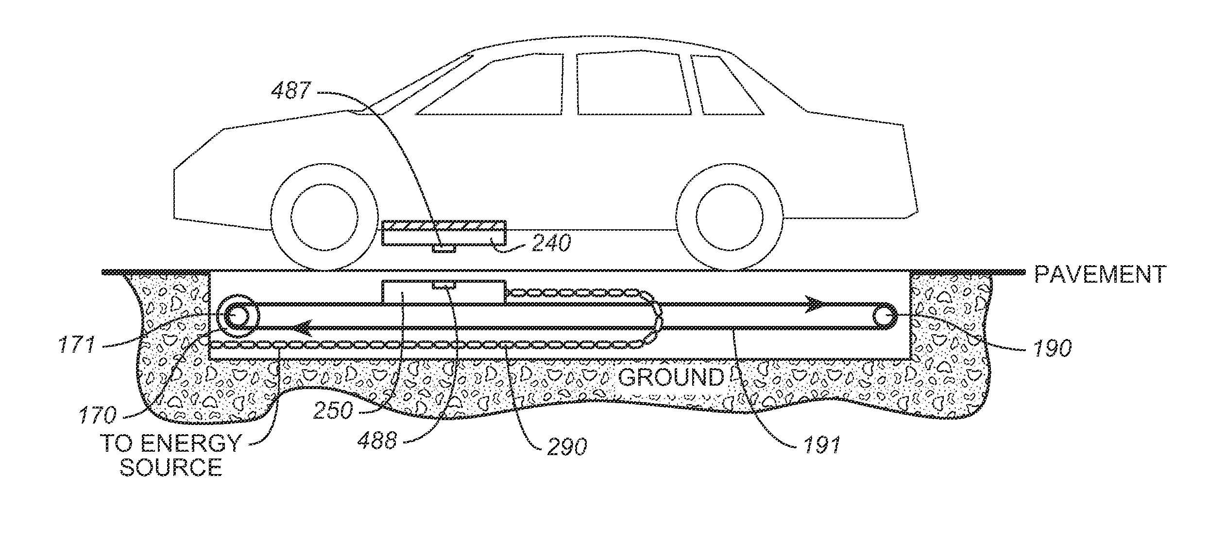
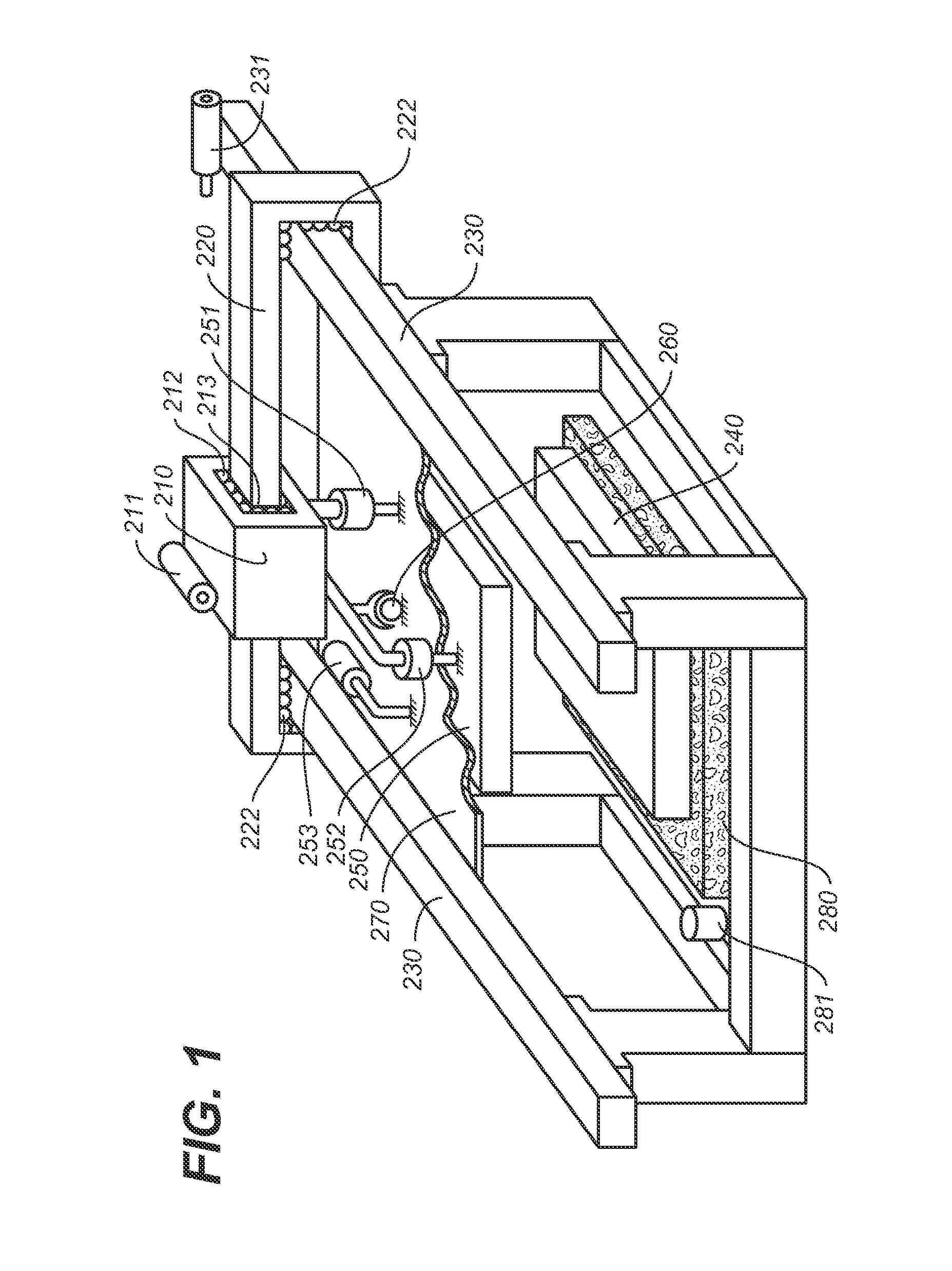
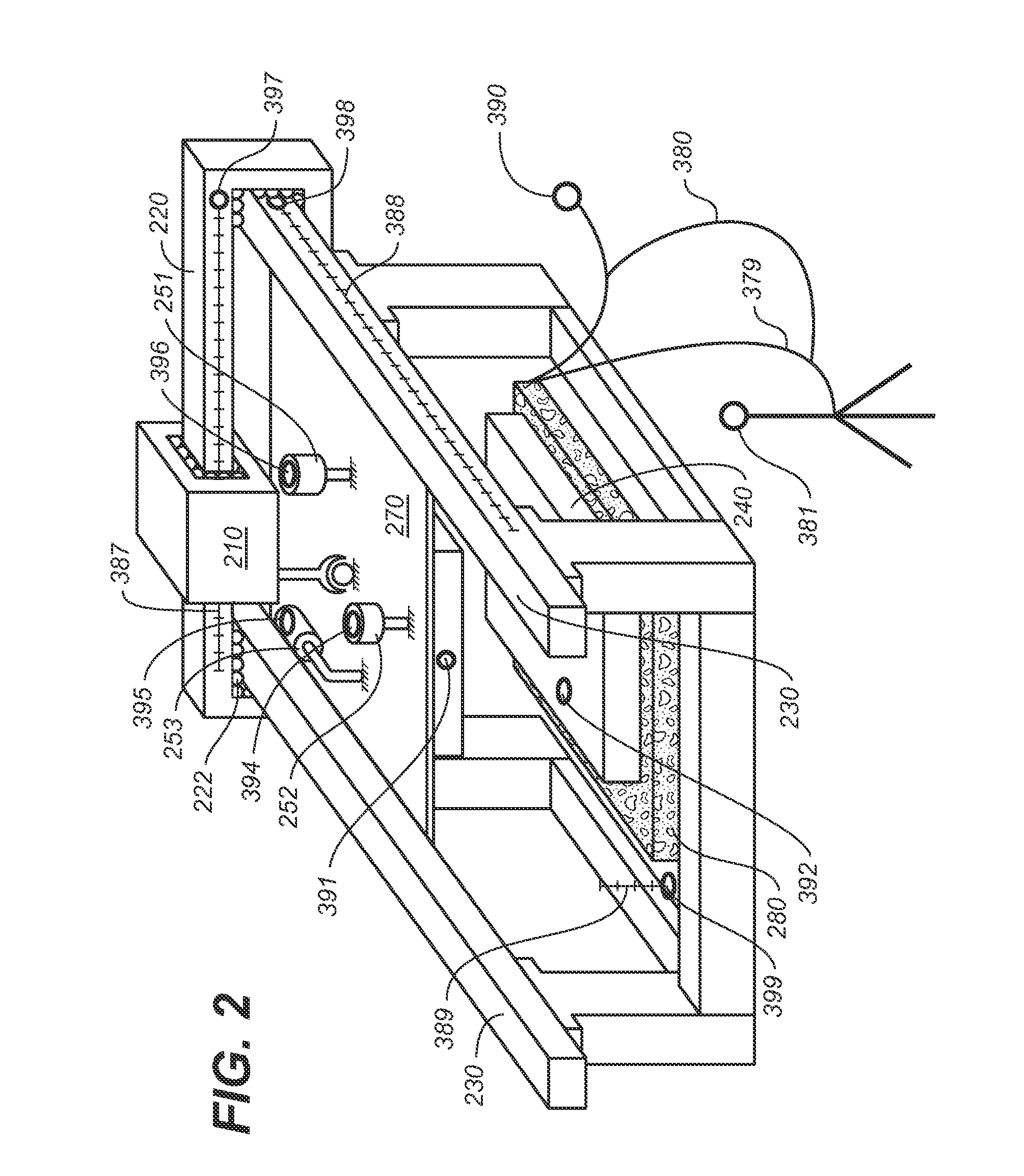
[0027]The invention is composed of a coordinate positioning and measuring frame that is computer programmable for the purpose of automatically running test procedures for the optimization and verification of high power wireless charging devices. By high power, we mean greater than 3 kilowatts. The frame employs the basic ideas behind a CNC multi-axis machine tool and coordinate measuring machine that are commonly used in manufacturing. It employs servo drives and / or other actuators for positioning and encoders and scales for precisely measuring position but has been adapted to position and record location and orientation information of a charge coupler device's magnetic resonance coils. To this end, the frame of the apparatus, as will be described in detail infra, must be ridged enough to support the weight of the charging coil modules and have powerful enough drives to move and position the modules. Exemplary materials useful for this purpose include aluminum, steel, concrete, and ...


PUM


Abstract

Provided are a method and apparatus and method for the alignment, verification and optimization of wireless charging systems manufactured for use and used with electric vehicles. With some minimal modifications the same apparatus may be used to align a charging coil mounted on a vehicle with a charging coil, mounted on or in an electric vehicle charging bay or parking space, or to verify and optimize manufactured wireless vehicle charging system elements before they are installed.

Description

FIELD OF THE INVENTION[0001]The invention concerns high power wireless charging systems, particularly the wireless charging of electric vehicles. More specifically the invention provides an apparatus and method for the alignment, verification and optimization of wireless charging systems manufactured for use and used with electric vehicles.BACKGROUND[0002]Fully electric and hybrid (for example, gas and electric and fuel-cell and electric) vehicles in existence today typically require charging via plug-in cables that are manufactured in accordance with international standards. (The term “electric vehicle” as used here is intended to encompass both fully electric and hybrid vehicles.) This conductive connection requires the vehicle operator to plug a charging cable into the vehicle. The cable must remain connected to the vehicle during the charging process. One disadvantage of this approach is that it requires the use of high voltage cables. Frayed or damaged cables create a hazardous...

Claims


Application Information

Patent Timeline
Patent Type & Authority Applications(United States)
IPC IPC(8): B60L11/18
CPCB60L11/182Y02T90/12Y02T90/14Y02T10/7072B60L2240/667Y02T90/16B60L53/30B60L53/38B60L53/126H02J50/90H02J7/0042Y02T10/72Y02T10/70H02J50/12B60L53/12
Inventor SCHNEIDER, JESSE M.O'HARE, JONATHAN J.
Owner WIRELESS CHARGE
Why Eureka
Try Eureka