Pressurized water reactor depressurization system

a pressurized water and reactor technology, applied in nuclear reactors, nuclear elements, greenhouse gas reduction, etc., can solve the problems of increasing the rate of nuclear reaction and core power, reducing the extent of neutron absorption, and reducing the size of the reactor, so as to reduce the pressure within the reactor and reduce the opening

Inactive Publication Date: 2014-08-28
WESTINGHOUSE ELECTRIC CORP
View PDF1 Cites 7 Cited by
  • Summary
  • Abstract
  • Description
  • Claims
  • Application Information

AI Technical Summary

Benefits of technology

[0012]These and other objects are achieved by a nuclear power generation system having a reactor enclosed within a pressure vessel housed within a containment with the reactor operating at a higher pressure than the area surrounding the reactor within the containment. The reactor includes a depressurization system for reducing the pressure within the reactor by venting the coolant within the reactor into the containment. The depressurization system basically comprises an orifice within the pressure vessel for venting the coolant within the pressure vessel into the containment and a flow restrictor in flow communication with the orifice for restricting the critical flow rate of a fluid within the pressure vessel out of the orifice while enabling sufficient flow of a fluid to substantially equalize the pressure within the pressure vessel with the pressure outside the pressure vessel. Desirably, the flow restrictor has a reduced opening as compared to other conduits in the depressurization system, that is gauged to provide the minimum critical flow required by the depressurization system to maintain the reactor core covered with coolant. Preferably, the flow restrictor is a venturi having a gradual transition between a maximum diameter and a minimum diameter of an opening through the venturi within which the depressurization is communicated.

Problems solved by technology

Inserting a control rod further into the core causes more neutrons to be absorbed without contributing to the fission reaction in an adjacent fuel rod; and retracting the control rods reduces the extent of neutron absorption and increases the rate of the nuclear reaction and the power output of the core.
If a major loss of coolant accident occurs, it is necessary to add coolant from a lower pressure supply containing a large quantity of water.
However, there is a potential that if the automatic depressurization system is activated in less dire circumstances, the containment may be flooded needlessly.
Depressurization followed by flooding of the reactor containment requires shutdown of the reactor and a significant cleanup effort.
It has been postulated that a spurious actuation of the automatic depressurization system under normal conditions could lead to an accident that is more severe than has been analyzed.

Method used


Image

  • Pressurized water reactor depressurization system
  • Pressurized water reactor depressurization system
  • Pressurized water reactor depressurization system

Examples


Embodiment Construction

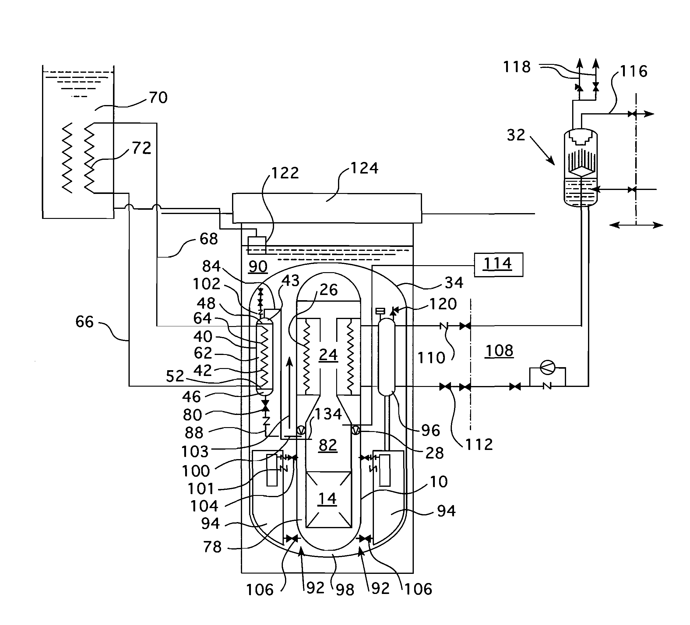
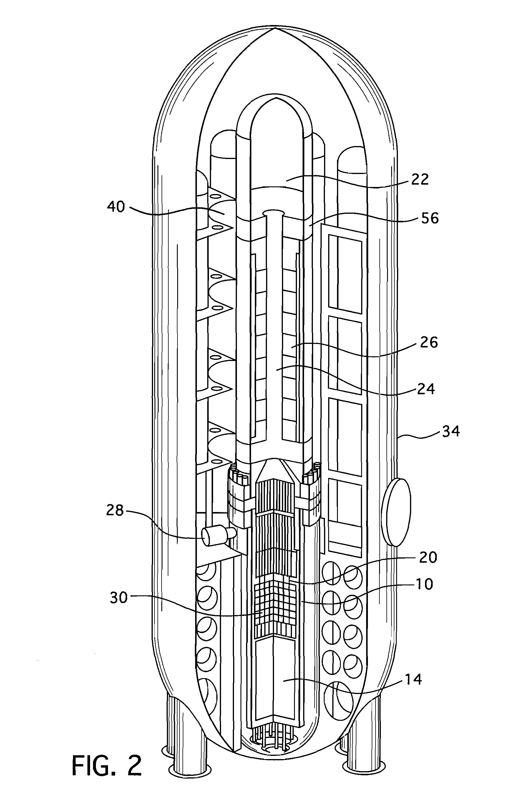
[0023]FIGS. 2, 3 and 4 illustrate a small modular reactor design having a passive heat removal system, high pressure water injection system, low pressure water injection system and recirculation system which benefits from this invention. FIG. 2 shows a perspective view of the containment of a modular reactor design to which this invention can be applied. The reactor containment illustrated in FIG. 2 is partially cut away, to show the reactor pressure vessel and its integral, internal components. FIG. 3 is an enlarged view of the reactor pressure vessel shown in FIG. 2. FIG. 4 is a detailed schematic view of one embodiment of the reactor which includes the major components of an extended passive core cooling and coolant recirculation system as well as some of the reactor auxiliary systems, including an ultimate heat sink and secondary heat exchange loop of the combined passive heat removal system and high head water injection system of one embodiment of the small modular reactor. Lik...


PUM


Abstract

A passive cooling system of a pressurized water reactor that relies on a depressurization system to reduce the pressure in the reactor vessel in the event of a loss of coolant accident and vent the steam generated by the decay heat of the reactor core in a post loss of coolant accident stage. The depressurization results in a low pressure difference between the reactor vessel and the containment and enables gravity driven cooling system injection into the reactor vessel. The depressurization system includes a flow restrictor within an orifice in the reactor vessel wall that connects to a vent pipe which forms a flow path between the interior of the reactor vessel and the containment atmosphere when a valve within the vent pipe is in an open position. Preferably, the flow restrictor is a venturi that has a gradual contraction and a gradual expansion in the flow path area.

Description

BACKGROUND[0001]1. Field[0002]This invention relates generally to nuclear reactors and in particular to pressurized water nuclear reactor systems having passive safety features with automatic depressurization of the reactor coolant circuit to facilitate the injection of additional cooling water into the cooling circuit.[0003]2. Related Art[0004]In a nuclear reactor for power generation, such as a pressurized water reactor, heat is generated by fission of a nuclear fuel such as enriched uranium, and transferred to a coolant flowing through a reactor core. The core contains elongated nuclear fuel rods mounted in proximity with one another in a fuel assembly structure, through and over which the coolant flows. The fuel rods are spaced from one another in co-extensive parallel arrays. Some of the neutrons and gamma rays released during nuclear fission in a given fuel rod pass through the water moderator in between fuel rods and impinge on fissile material in adjacent fuel rods, contribu...

Claims


Application Information

Patent Timeline
Patent Type & Authority Applications(United States)
IPC IPC(8): G21C9/004
CPCG21C9/004G21C1/086G21C1/322G21C15/18Y02E30/30
Inventor LIAO, JUNKUCUKBOYACI, VEFA N.
Owner WESTINGHOUSE ELECTRIC CORP
Why Eureka
Try Eureka