Optical device and system for solid-state lighting

a technology of optical devices and solid-state lighting, applied in semiconductor devices for light sources, lighting and heating apparatus, lighting and heating arrangements, etc., can solve the problems of increasing manufacturing costs, complex geometry of these structures, complex structures and expensive design and manufacturing

Active Publication Date: 2014-09-18
1947796 ONTARIO INC
View PDF11 Cites 23 Cited by
  • Summary
  • Abstract
  • Description
  • Claims
  • Application Information

AI Technical Summary

Benefits of technology

[0033]The optical device is preferably compact and light weight. For example, in one embodiment for an A19-type light bulb, the cone optic has a base diameter of 25 mm or less, and an overall height of 25 mm or less, and the outer cone surface has an axial height of 20 mm or less. In preferred embodiments, body defined between the inner and outer cone surfaces is relatively thin and has a substantially uniform thickness from the base to the apex, e.g. 1 mm-2 mm thickness including facets or grating structures. This facilitates molding and requires less material for fabrication. It is preferably lightweight, e.g. having a weight of less than 2 g, and preferably less than 1.5 g.
[0034]The relatively thin body, and ventilation holes assist in thermal dissipation, and help to avoid hot spots and heat stresses, which can contribute to thermal degradation during prolonged operation.
[0037]Thus, optical devices and systems according to the present invention mitigate one of more disadvantages of known optical elements and light guides for generating omni-directional light distributions from LED light sources for solid-state lighting applications.

Problems solved by technology

Although some of the light guides disclosed in these references provide for omni-directional light distributions over a very wide angle, the geometry of these structures is complex.
The multiple facets with multi-directional forward and backward facing surfaces make these structures complex and expensive to design and manufacture, requiring complex mold tools, multistep molding and finishing processes to produce the product.
Complex shapes with multiple opposing surfaces may require multi-part molds with seams, for example, that necessitate finishing or polishing of optical surfaces of the light guide after the molding process, which adds to manufacturing costs.
Apart from design and manufacturing issues, these complexly-shaped light guides have multiple reflective / refractive surfaces or facets that intersect at acute angles.
The sharp angles, between opposing reflective surfaces can generate significant discontinuities or undulations in the angular distribution of the light intensity.
These discontinuities may be apparent as artifacts in the light distribution, such as brighter and darker fringe patterns that are visible to the human eye and / or which may be unacceptable for applications requiring uniform or even lighting.
Thus, although many light guides, light pipes, and non-imaging optics have been proposed to provide a wider angular distribution from an LED light source, many do not meet the requirements established by existing lighting standards and / or are complex and expensive to manufacture.
Another issue is that in the above referenced structures, the light guide typically comprises a transparent optical grade polymer material, such as PMMA (polymethyl methacrylate) that can degrade during extended use at high temperatures.
Therefore, the polymer material is exposed to elevated temperatures that contribute to aging or premature breakdown of the material, which over time can degrade the optical properties, such as the refractive index, and decrease the useful operational life span.
Existing light guides do not effectively address these issues of thermal stresses or thermal degradation.
Thus, there is a need for improved or alternative optical elements or light guides that address one or more issues of cost, manufacturability, low transmission efficiency, limited luminous efficiency and uniformity, and poor thermal management.

Method used


Image

  • Optical device and system for solid-state lighting
  • Optical device and system for solid-state lighting
  • Optical device and system for solid-state lighting

Examples


first embodiment

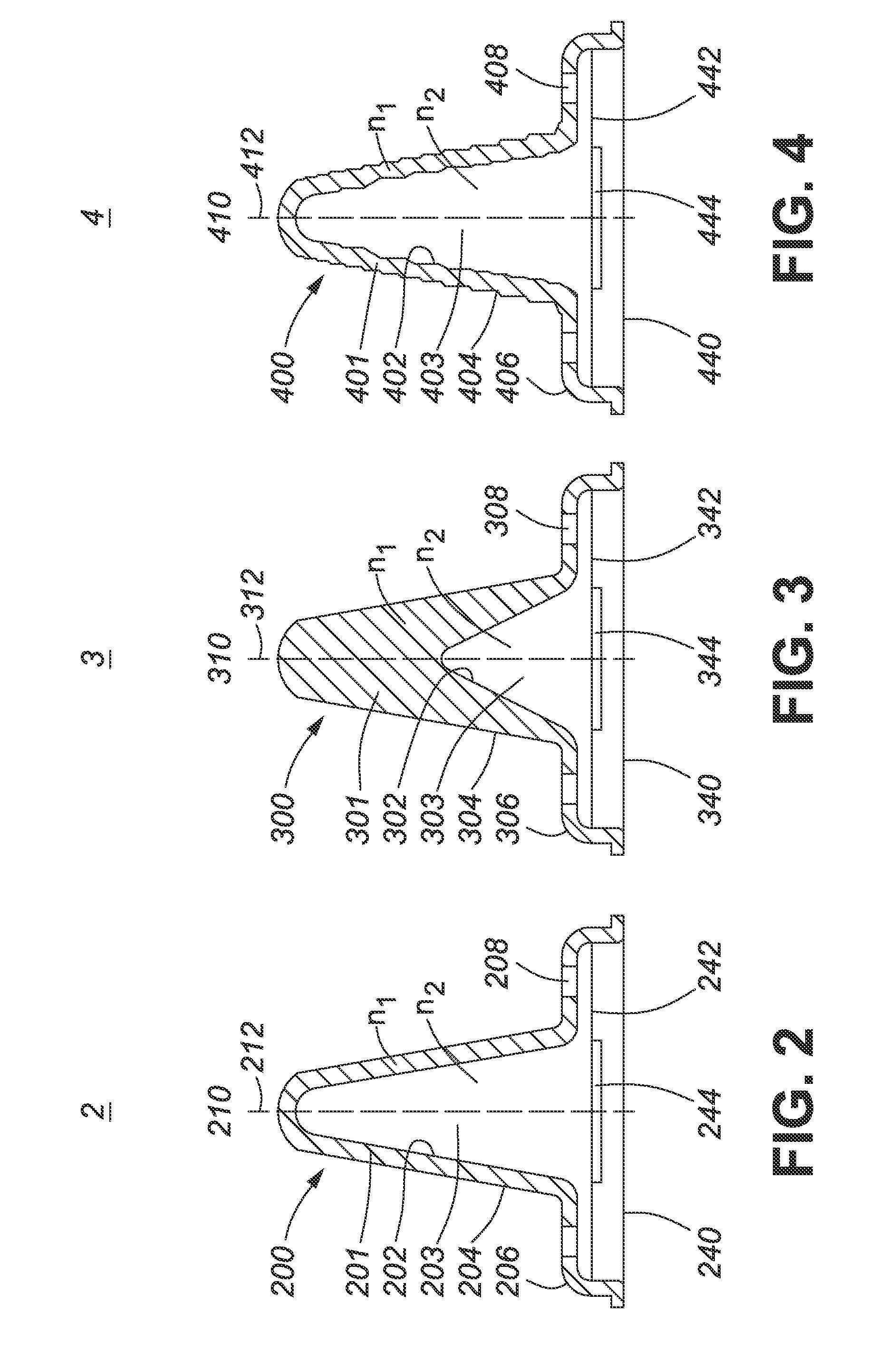
[0065]FIG. 2 shows a schematic cross-sectional view of an optical device 2 comprising a cone light pipe or light guide similar to the optical device 1 shown in FIG. 1 (to facilitate comparison, corresponding parts are labelled with the same reference numerals incremented by 100). The light guide 2 has a generally conical form and comprises a body 200 of an optically-transparent material comprising a first, inner cone surface 202 and a coaxial second, outer cone surface 204. The surfaces have rotational symmetry around the vertical axis 210 (z-direction) of the cone. Each of the first and second cone surfaces 202 and 204, respectively, extend upwardly and converge to a rounded tip 212 at the apex of the conical body 200, and thus, define an outer cone 201, and an inner cone cavity 203.

[0066]A simplified view of part of the body 200, to illustrate parameters defining the structure, is shown in FIG. 7A. That is, the inner cone surface 202, defining the inner cone cavity 203, is define...

second embodiment

[0068]FIG. 3 shows a schematic cross-sectional view of a cone light guide 3 according to a The light guide 3 is similarly defined by parameters Φ, Θ, r, R, h, H, d, D, as indicated in FIG. 7A. The outer form of the light guide 3, defined by outer conical surface 304, having an outer cone angle Θ, similar to that of light guide 2 shown in FIG. 2. However, the inner conical surface 302 has a larger cone angle Φ and tapers to a rounded tip 314 at a height h about half the height H of the rounded tip 312 of the outer cone surface 304, which results in a smaller inner cavity 303. As illustrated, the thickness of conical body 300 of the light guide 3 therefore increases gradually from a base portion 306 to the inner apex 314, and then rapidly to the solid upper tip 312 of the outer cone 301. The base portion 306 also comprises ventilation apertures 308. The cavity 303 is air filled, i.e. refractive index n2=1 and aligns over an LED emitter area 344 of an LED light source 340. The conical...


PUM


Abstract

An optical device for transforming an input light distribution from an LED light source to provide an omni-directional output light distribution for solid-state lighting is disclosed. The optical device has a conical form, comprising first and second coaxial cones of different refractive index, defined by coaxial inner and outer cone surfaces, which converge from a cone base to a rounded tip at the apex. Preferably, each of the inner and outer cone surfaces comprises a plurality of conical facets defining a grating structure. The inner cone, i.e. air cavity, is directly coupled to an LED emitter area. Cone angles and spacings of conical facets, defining inner and outer gratings, are tailored to reshape a predetermined input light distribution. Apertures assist in heat dissipation. A lightweight, compact device with high transmission efficiency can be manufactured at low cost by one-step injection molding from an optical-grade polymer, such as PMMA.

Description

CROSS-REFERENCE TO RELATED APPLICATIONS[0001]This application claims priority from U.S. Provisional Application No. 61 / 786,743, of the same title, filed Mar. 15, 2013, which is incorporated herein by reference in its entirety.TECHNICAL FIELD[0002]The present invention relates to solid-state lighting, and particularly to optical systems comprising a solid-state light-emitting device (LED) and an optical device, such as a light guide or light pipe, for providing a desired light distribution, for example, an omni-directional light distribution suitable for solid-state lighting applications.BACKGROUND ART[0003]In line with a global trend towards improved energy efficiency and energy conservation, the lighting industry is moving from incandescent lighting to alternative, more energy-efficient light sources. Solid-state light-emitting devices (LEDs), such as light-emitting diodes, have evolved rapidly in recent years and are now available with high brightness and suitable color rendering ...

Claims


Application Information

Patent Timeline
Patent Type & Authority Applications(United States)
IPC IPC(8): F21V5/00F21V29/00
CPCF21V29/004F21V5/00F21V3/00F21V5/04F21V29/773F21K9/232F21K9/60F21Y2115/10F21V29/83Y02B20/30
Inventor SUN, JIEHART, CHRISTOPHERNAOR, STEPHEN
Owner 1947796 ONTARIO INC
Why Eureka
Try Eureka