System and Method for H2S Removal Integrated with Stinson Process CO2 Removal

a technology of stinson process and co2 removal, applied in the direction of separation processes, liquid degasification, gaseous fuels, etc., can solve the problems of limiting the ability to use co2 /sub>waste stream for flooding operations, waste stream amount, etc., to facilitate the economically efficient and selective removal of h2s, reduce operating costs through fuel savings, and increase overall process efficiencies

Active Publication Date: 2014-09-18
BCCK HLDG CO
View PDF1 Cites 11 Cited by
  • Summary
  • Abstract
  • Description
  • Claims
  • Application Information

AI Technical Summary

Benefits of technology

[0007]The system and method disclosed herein facilitate the economically efficient and selective removal of H2S from a feed gas stream containing methane and CO2 using a solvent. The system and method of the invention are particularly suitable for integrated use in connection with the Stinson Process for removing CO2, wherein the solvent used to remove the H2S is different from the solvent used to remove CO2 and the majority of the H2S is removed upstream from the CO2 removal. Natural gas processing using the prior art Stinson Process, with around 3.5% H2S in the feed stream, generally results in a sales gas (hydrocarbon) stream containing no CO2 (or less than 4 ppm CO2) and around 4 ppm of H2S, and a CO2 waste stream containing around 47,000 ppm H2S. The methanol stripping in the Stinson Process will reduce the level of H2S from 3.5% in the feed to around 0.03% (300 ppm), which is further reduced to 4 ppm or less after passing through a molecular sieve to produce an acceptable sales gas. While the amount of H2S in the sales gas stream may be within pipeline specifications, the amount in the waste stream limits the ability to use the CO2 waste stream for flooding operations. Typically, the H2S specification for CO2 flood streams is less than 100 ppm. Removing the majority of the H2S upstream of the Stinson Process according to the invention increases the overall process efficiencies, including a reduction in operating costs through fuel savings, while allowing production of a processed CO2 stream from the Stinson Process that is well within specifications for allowing use of that stream in flooding operations. The processed CO2 stream can also be delivered to the pipeline as a liquid stream, which has significant cost savings over injecting as a vapor. By reducing the H2S level in the Stinson Process feed to a preferable level less than 50 ppm, it may be unnecessary to use a molecular sieve after the Stinson Process to achieve a sales gas stream with an acceptable H2S level, which may offset some of the capital costs associated with the invention and saves on operating costs. Additionally, the use of two different solvents, a first solvent to remove H2S and a second solvent to remove CO2, where the solubility of H2S relative to CO2 in the first solvent is greater than the relative solubility in the second solvent, further increases the efficiencies of the overall process.
[0008]Through the use of the invention, the 3.5% (35,000 ppm) H2S typically found in the Stinson Process feed stream is substantially reduced. According to the invention, the processed gas stream that feeds the Stinson Process fractionating column preferably contains less than 50 ppm (0.005%) of H2S, but may contain up to 150 ppm or more H2S depending on the amount of H2S in the gas stream feeding the system of the invention, although the amount of H2S is still significantly less than the 35,000 ppm in a typical Stinson feed stream. Consequently, only trace amounts of H2S are present in the final sales gas (hydrocarbon) stream and in the processed CO2 stream using the H2S removal methods according to the invention integrated with the Stinson Process. Additionally, the concentrated CO2 waste stream in the typical Stinson Process has around 94% CO2 and 5% H2S, which is too much H2S to allow use of the CO2 in flooding operations, but not enough H2S to allow for recovery of sulfur—making it truly a waste stream. By first reducing the H2S level in the Stinson feed according to the invention, the processed CO2 stream produced from the Stinson Process fractionating column has sufficiently low levels of H2S to permit use in flooding operations. Additionally, the acid gas stream of the present invention contains 0.5%-50% (or more) H2S, but preferably contains at least 30% H2S. The amount of H2S in the acid gas stream will depend on the amount of H2S in the stream that feeds the system of the invention. The preferred higher concentration levels for H2S in the acid gas stream of the present invention make that stream suitable for feeding a Claus Process to recover sulfur from the H2S, if desired. Thus the use of the invention integrated with the Stinson Process allows reuse of what would otherwise be waste streams with prior art processes. Alternatively, the volume of the acid gas stream according to the invention is relatively smaller than a traditional Stinson Process acid gas (CO2 waste) stream, making it easier to dispose of the H2S if further processing is not desired.
[0010]According to another embodiment of the invention, nitrogen is fed to the stripper to enhance separation of the DEPG from the CO2 and H2S. Preferably, the nitrogen is supplied from an onsite Nitech™ NRU (such as that described in U.S. Pat. No. 5,141,544), to provide enhanced efficiencies; but other sources of nitrogen may be used. Typically, water or steam is used to regenerate the DEPG. The addition of nitrogen to the stripper enhances the recovery of the DEPG when operating in an anhydrous mode, according to a preferred embodiment of the invention. Additionally, an anhydrous operation results in further cost savings, since lower cost metals may be used in equipment fabrication.
[0011]There are several advantages to the system and method disclosed herein not previously achievable by those of ordinary skill in the art using existing technologies. These advantages include, for example, the system and method allow for the CO2 stream produced through the Stinson Process to be within pipeline specifications for use in flooding operations, rather than be treated as a waste stream requiring disposal. The system and method also allow for removal of the corrosive H2S prior to processing in the Stinson Process and results in an acid gas stream having sufficiently high concentration of H2S to allow further processing for recovery of sulfur, if desired. By integration with common utilities utilized by the Stinson Process, the cost of new equipment is reduced. Because the H2S is highly soluble in the methanol used in the Stinson Process, the removal of the H2S prior to the Stinson Process will enhance the removal of CO2 in the Stinson Process. Additionally, the system and method of the invention require low regeneration of heat, using only 30%-50% of the energy required for conventional technologies to separate out H2S. The system and method of the invention are particularly well suited for feed streams containing 20% or more CO2.
[0012]Although the present system and method has the disadvantage of higher capital costs associated with additional equipment for the H2S removal, the costs of such are sufficiently offset by the savings in having a usable Stinson Process CO2 stream and savings in operating costs achieved by strategically placing the H2S removal upstream of the Stinson Process to take advantage of inter-operational efficiencies.

Problems solved by technology

While the amount of H2S in the sales gas stream may be within pipeline specifications, the amount in the waste stream limits the ability to use the CO2 waste stream for flooding operations.
Additionally, the concentrated CO2 waste stream in the typical Stinson Process has around 94% CO2 and 5% H2S, which is too much H2S to allow use of the CO2 in flooding operations, but not enough H2S to allow for recovery of sulfur—making it truly a waste stream.

Method used


Image

  • System and Method for H2S Removal Integrated with Stinson Process CO2 Removal
  • System and Method for H2S Removal Integrated with Stinson Process CO2 Removal
  • System and Method for H2S Removal Integrated with Stinson Process CO2 Removal

Examples


example

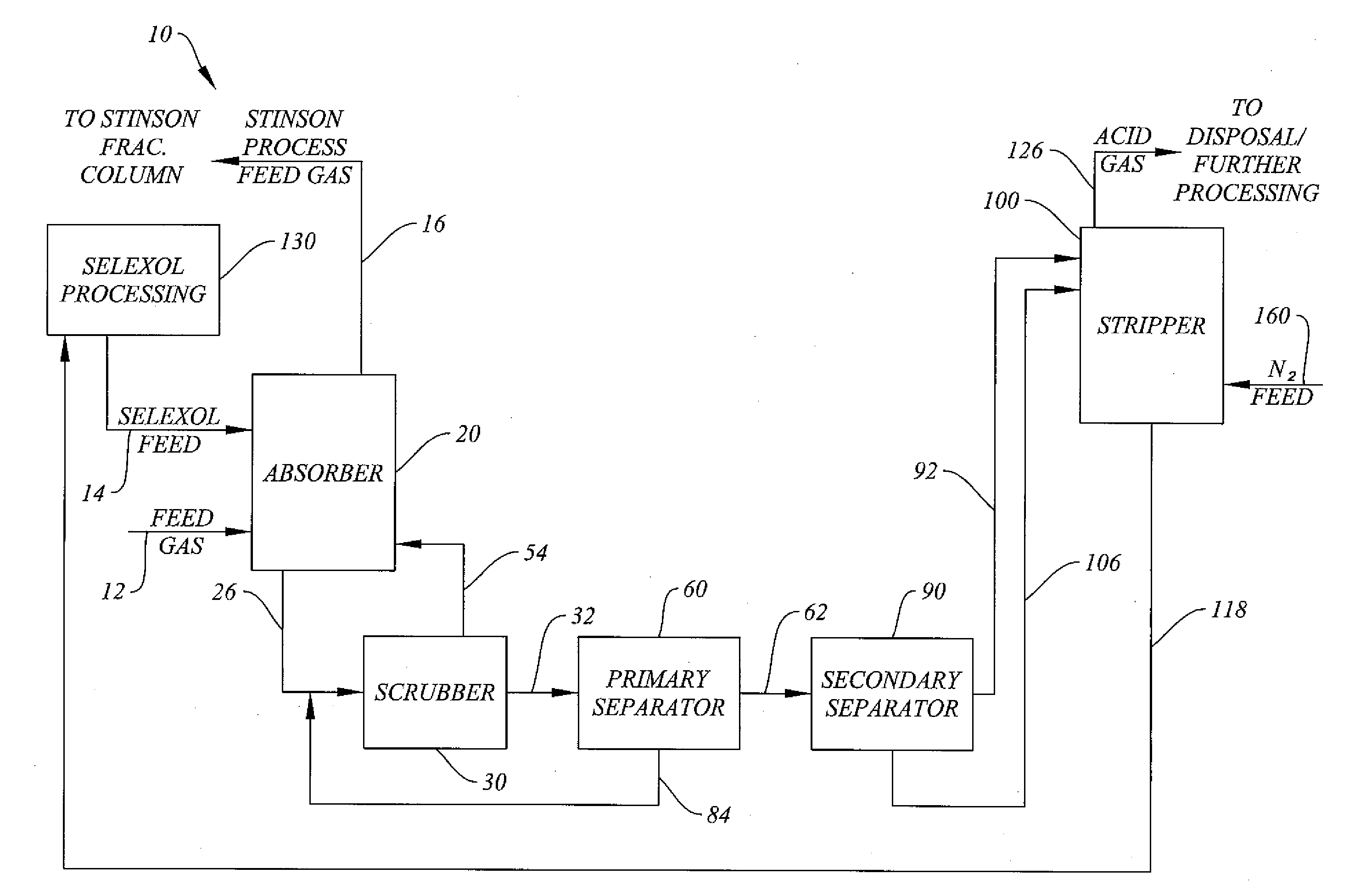
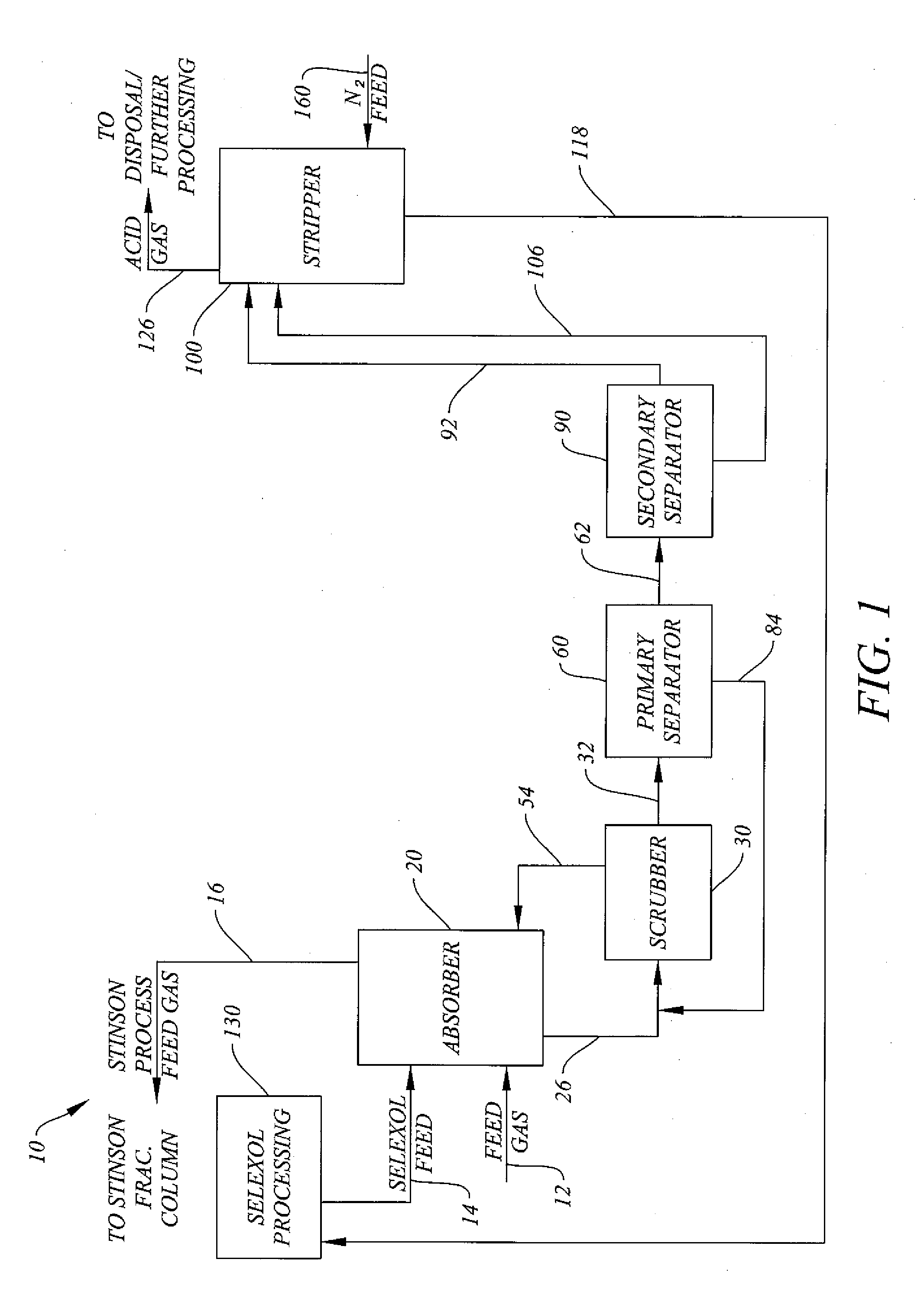
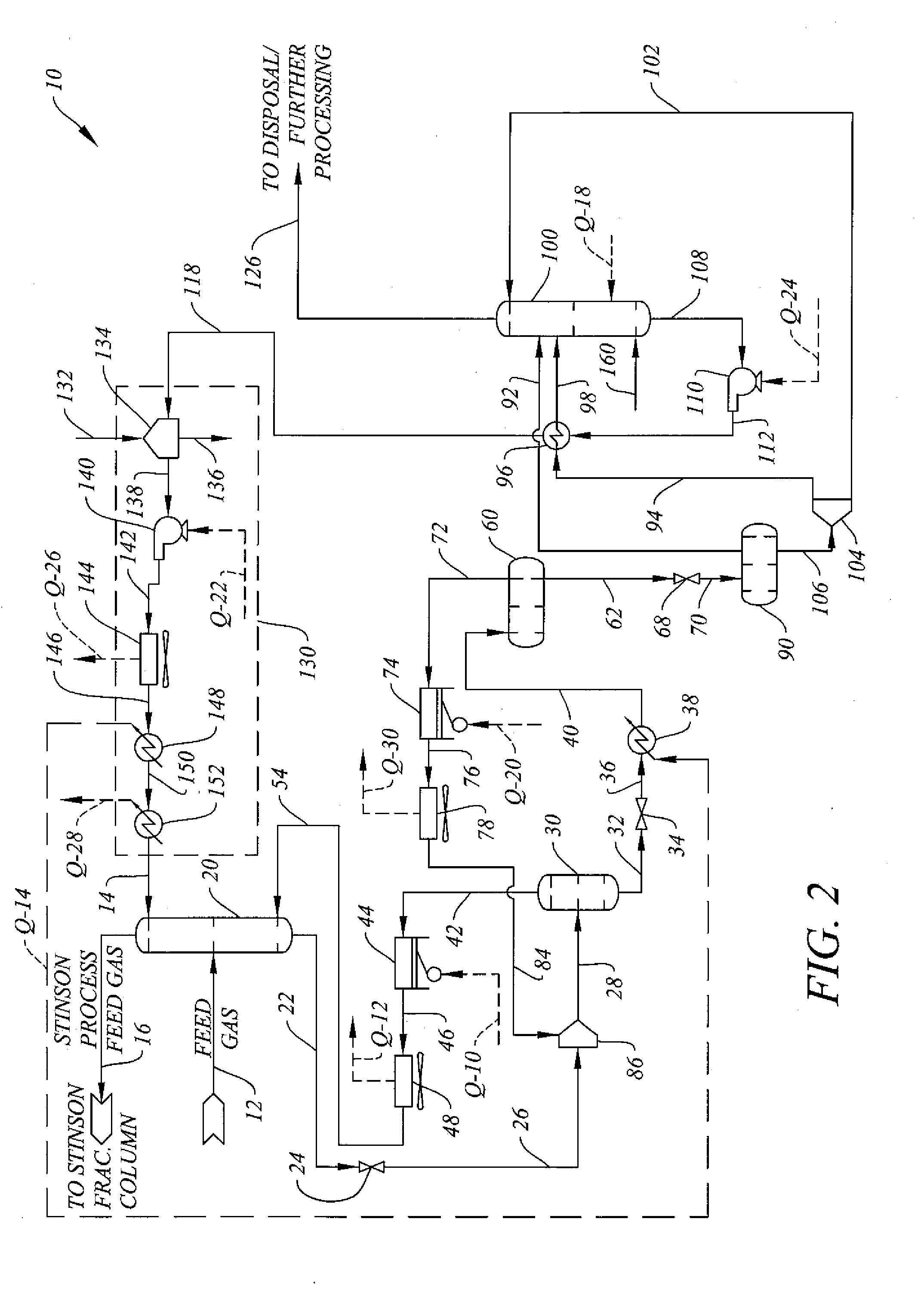
[0027]The flow rates, temperatures and pressures of various simulation flow streams referred to in connection with the discussion of the system and method of the invention in relation to FIG. 2 for a feed gas stream flow rate of approximately 200 MMSCFD and containing 7% nitrogen, 19.5% methane, 69.1% CO2, and 3.7% H2S appear in Table 1 below. The values for the energy streams referred to in connection with the discussions of the system and method of the invention in relation to FIG. 2 appear in Table 2 below. The values discussed herein and in the tables below are approximate values.

TABLE 1FLOW STREAM PROPERTIESStream FlowRef.%%%RateTemp.Press.No.% N2 CO2H2S% CH4 DEPG(lbmol / h)(deg. F)(psia)12769.1 3.719.502195679.9671.9140.09800.012099.89 4889.340700167.7700.002 21.5neg19889.1 95.4670.122neg55.4 7.9 0.00736.613350.3110.1672.126neg55.4 7.9 0.007 36.613350.38631028neg62.1 7.80.0063016306.5 8731032neg40.3 10.30.000549.39910.386.630536neg40.3 10.30.000549.39910.366.512040neg40.3 10.30....


PUM

PropertyMeasurementUnit
temperatureaaaaaaaaaa
pressure dropaaaaaaaaaa
temperatureaaaaaaaaaa

Abstract

A system and method for efficiently removing hydrogen sulfide from a natural gas feed stream to produce a Stinson Process feed stream and an acid gas stream. A first solvent separates the majority of the carbon dioxide and hydrocarbons from the hydrogen sulfide in the natural gas feed to produce the Stinson feed stream. By removing the majority of the hydrogen sulfide prior to feeding the Stinson Process, a carbon dioxide stream suitable for use in flooding operations may be produced with the Stinson Process. The system and method also increase the concentration of hydrogen sulfide in the acid gas stream, making it suitable for sulfur recovery operations. The system and method are particularly suitable for natural gas feed streams containing 0.5%-20% hydrogen sulfide and at least 20% carbon dioxide. Operation in an anhydrous mode with the addition of nitrogen aids in solvent recovery for recycling.

Description

BACKGROUND OF THE INVENTION[0001]1. Field of the Invention[0002]This invention relates to a system and method for removing hydrogen sulfide from carbon dioxide, methane and other components of natural gas streams being processed into a sales gas stream. The system and method of the invention are particularly suitable to separate carbon dioxide and hydrogen sulfide when the Stinson Process is utilized for removing high concentrations of carbon dioxide and hydrogen sulfide from natural gas streams containing nitrogen.[0003]2. Description of Related Art[0004]Hydrogen sulfide and carbon dioxide contamination are frequently encountered problems in the production of natural gas. Transporting pipelines typically do not accept natural gas containing more than about 4% CO2 and 4 ppm hydrogen sulfide. Hydrogen sulfide is particularly problematic because it is extremely toxic to humans and is corrosive in nature. Allowing hydrogen sulfide to remain in process streams can be harmful to piping a...

Claims


Application Information

Patent Timeline
Patent Type & Authority Applications(United States)
IPC IPC(8): C07C7/11B01D53/14C07C7/04
CPCC07C7/11C07C7/04B01D53/1425B01D53/1418B01D53/1468B01D2252/2026B01D2256/24C10L3/103C10L3/104Y02C20/40
Inventor BUTTS, RAYBURN C.
Owner BCCK HLDG CO
Why Eureka
Try Eureka