Temporary valve and valve-filter

a technology of valve filter and valve valve, which is applied in the field of temporary valve and valve filter, can solve the problems of human heart valve degeneration, prolonged recovery time, and high invasiveness, and achieve the effects of preventing wide open regurgitation of blood, and reducing the risk of emboli escap

Active Publication Date: 2014-09-18
VALVE MEDICAL
View PDF17 Cites 28 Cited by
  • Summary
  • Abstract
  • Description
  • Claims
  • Application Information

AI Technical Summary

Benefits of technology

[0016]Advantages that may be achieved by the present invention include combined maintenance of blood flow and minimization of emboli in the blood stream requiring deployment of a single device. The installation of the percutaneous temporary valve-filter before commencing percutaneous vascular procedures, such as implanting a permanent percutaneous prosthetic device or repairing a native valve, may alleviate the time pressure for such further procedures by preventing wide open regurgitation of blood. In other words, the temporary valve or temporary valve-filter device of the invention permits stabilization of the system during a valve replacement or valve repair procedure. For example, when used during replacement with a modular percutaneous valve device, the temporary valve provides sufficient time to deploy and dock the valve modules into the modular frame. The embolic filter function of the temporary valve-filter of the invention minimizes the escape of emboli that may be generated during a percutaneous procedure thereby avoiding embolic blockage of the blood vessels. As such, the valve-filter device of the invention may improve the safety and outcome of percutaneous cardiovascular procedures.

Problems solved by technology

However, human heart valves can degenerate for a variety of reasons.
The standard surgical procedure involves the opening of the patient's thoracic cavity, which is highly invasive and requires cardiopulmonary bypass and prolonged recovery time.
Additionally, the manipulation of the delivery device, repair tools and / or valve device during a percutaneous valve repair or valve replacement procedure may dislodge tissue and / or tissue adherents such as calcium deposits and / or generate thrombi.
This debris may form emboli that travel through the circulatory system and block smaller vessels, which can lead to severe complications, such as stroke, tissue ischemia or death.

Method used


Image

  • Temporary valve and valve-filter
  • Temporary valve and valve-filter
  • Temporary valve and valve-filter

Examples


Embodiment Construction

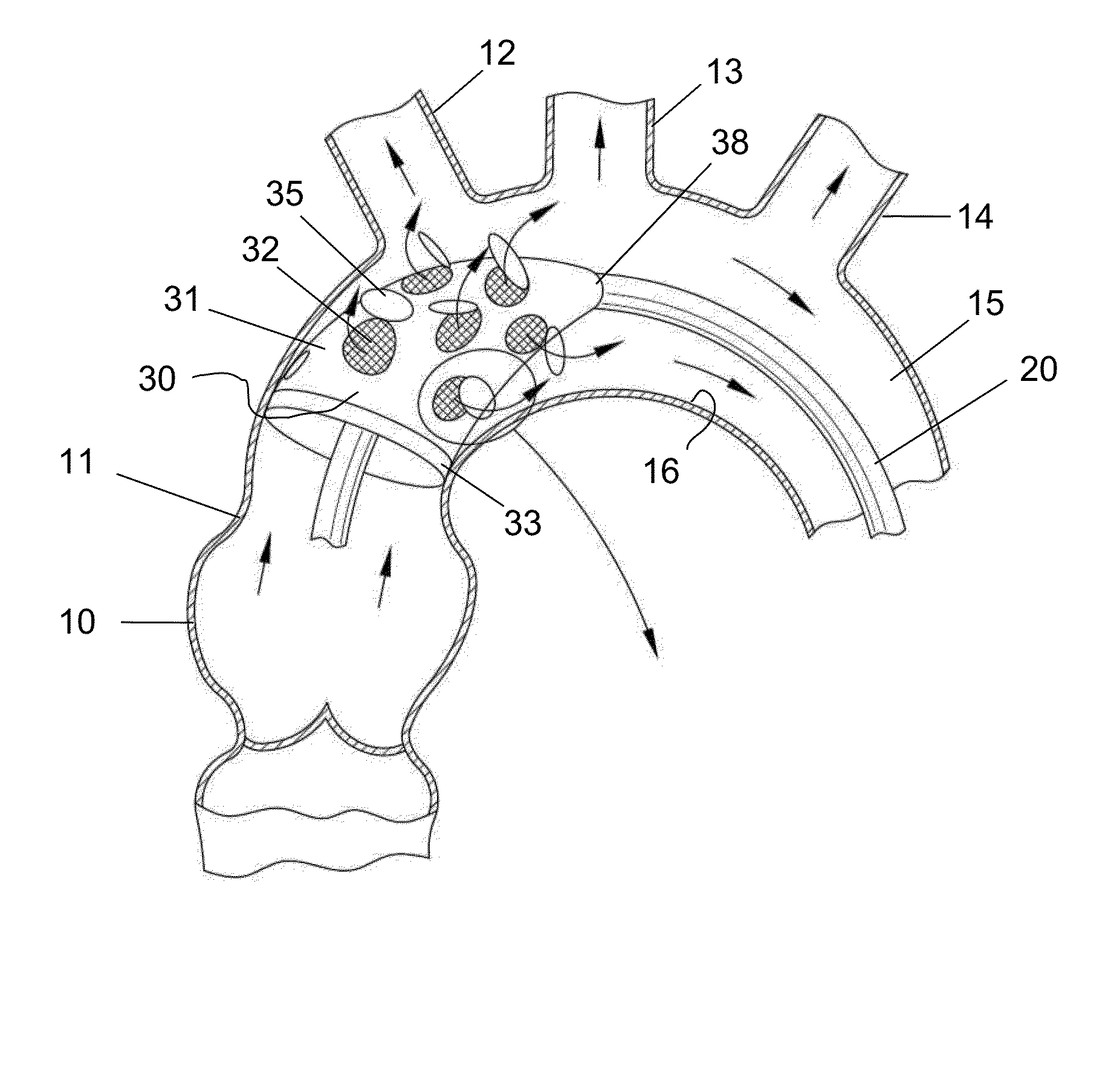
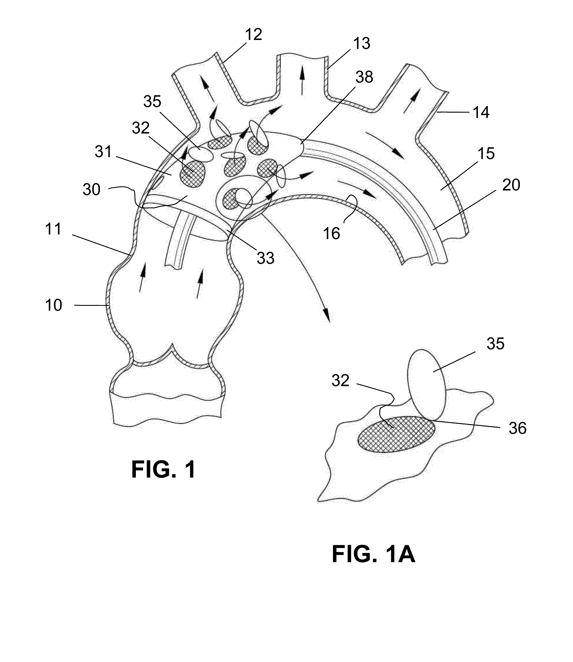
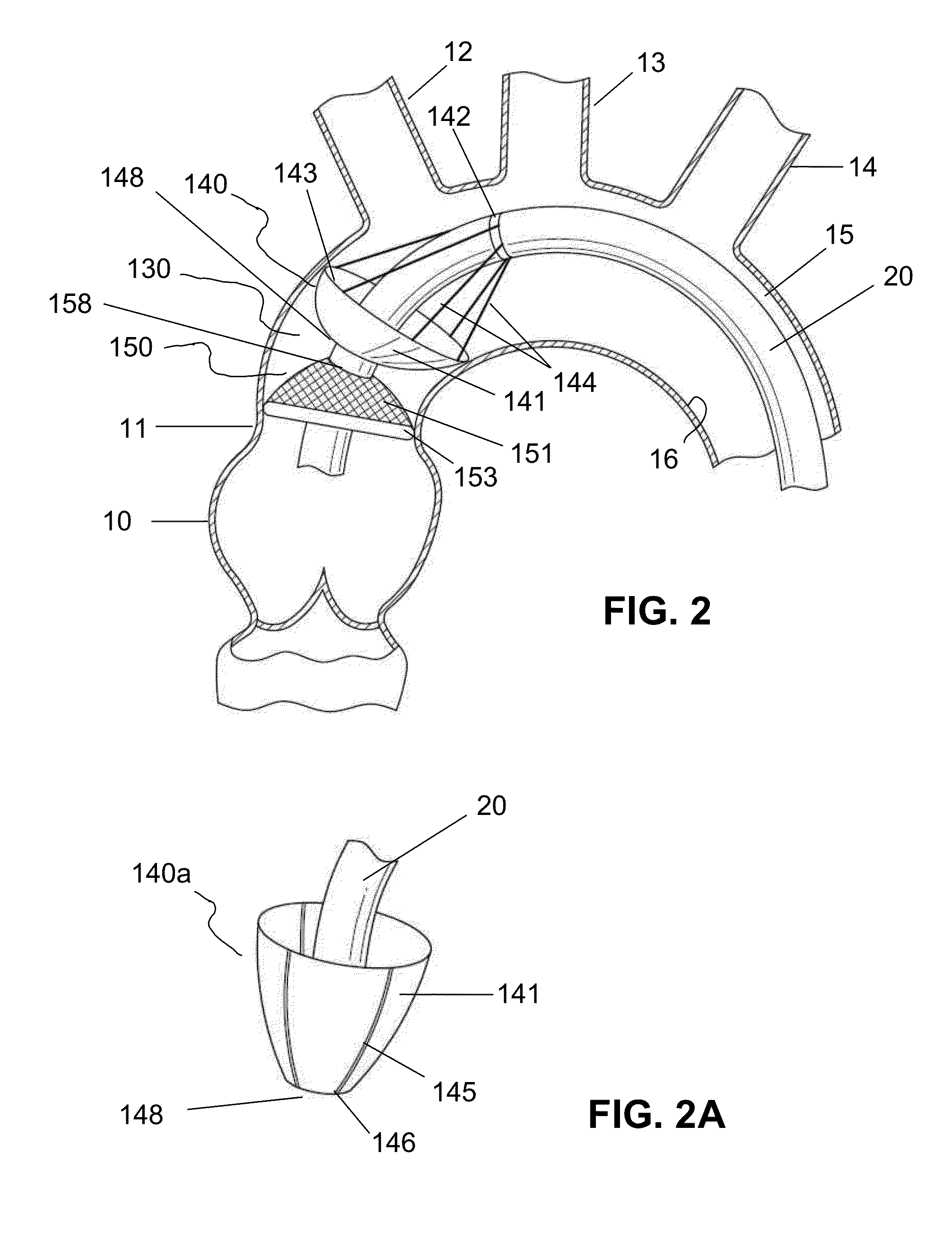
[0028]The present invention provides a percutaneous temporary valve-filter device and systems and methods for deploying the valve-filter device, for example in a blood vessel. The invention also provides a percutaneous temporary valve system and a method of deploying the temporary valve. The temporary valve system may be used with or without a filter unit.

[0029]The percutaneous temporary valve-filter device may be an integrated, or unitary, device—a device comprising one unit providing both valve and filtering functions, or it may be a multi-unit device comprising a valve unit and a filter unit that are separated or conjoined. In accordance with the invention, the percutaneous temporary valve filter device may have a variety of shapes from, for example, umbrella shaped to substantially flat. A substantially flat valve filter device may be, for example, disk shaped. The portion of the device that serves as valve is not porous to blood. The portion of the device that serves as a filte...


PUM


Abstract

A temporary percutaneous valve-filter device having valve portions non-porous to blood and filter portions non-porous to emboli but at least in part porous to blood. In one embodiment, the device has a substantially flat valve unit and a substantially flat filter unit. In another embodiment, the device has at least one open umbrella deployed configuration. In one aspect, the device has a unitary construction with one umbrella canopy with one or more filter areas with flaps allowing unidirectional blood flow. In another aspect, the device has a valve unit and filter unit, the umbrella canopies oriented in opposite directions, and the valve unit “closes” and opens to allow blood to flow to one direction. Also provided is a temporary valve system, including a core having an inverted delivery configuration and everted deployed configuration, that may be used with or without a filter unit, and a method of deployment.

Description

FIELD OF INVENTION[0001]The present invention relates to a temporary valve for maintaining normal blood flow and a temporary valve with embolic filter for maintaining normal blood flow while simultaneously trapping emboli during percutaneous cardiovascular procedures. The invention also relates to a system comprising such a valve or valve-filter device and a delivery device, and a method of deploying such a device.BACKGROUND OF THE INVENTION[0002]Valves are important structures in the human heart because they maintain blood flow in a single direction with minimal pressure loss. However, human heart valves can degenerate for a variety of reasons. A malfunctioning heart valve may be stenotic, where the leaflets of the valve do not open fully, or it may be regurgitant, where the leaflets of the valve do not close properly, or a combination of both. Valve repair and replacement procedures have thus been developed to either restore the function of the native valves or to implant a perman...

Claims


Application Information

Patent Timeline
Patent Type & Authority Applications(United States)
IPC IPC(8): A61F2/01A61F2/24
CPCA61F2/24A61F2/013A61F2/2427A61B17/1204A61B17/12109A61B17/12131A61B17/12177A61B2017/00243
Inventor RICHTER, YORAMWEISZ, ETYSCHWARZ, BOAZ
Owner VALVE MEDICAL
Why Eureka
Try Eureka