Reactants sprayed into plasma flow for rocket propulsion

a technology of reactants and plasma flow, which is applied in the field of reactants sprayed into plasma flow for rocket propulsion, can solve the problems of arcjets having a much lower thrust than pure chemical thrusters, and achieve the effects of increasing the thrust of rocket engines, increasing the specific impulse (isp) of the propellant(s) used, and being safer and/or less expensiv

Active Publication Date: 2014-10-02
LOCKHEED MARTIN CORP
View PDF6 Cites 12 Cited by
  • Summary
  • Abstract
  • Description
  • Claims
  • Application Information

AI Technical Summary

Benefits of technology

[0006]It is desirable to increase the thrust of a rocket engine by increasing the specific impulse (Isp) of the propellant(s) used by the engine. Some aspects of subject technology involve the recognition that a sufficient increase in the thrust may allow safer and / or less expensive rocket engines to replace of rocket engines that are less safe and / or more expensive.
[0007]Isp is the ratio of the force (thrust) produced to the weight flow of the propellant, and is related to the total thrust F by the equation:F=Isp{dot over (m)}g0   (1)wherein {dot over (m)} is the total mass flow rate of the propellant into the reaction chamber and g0 is the acceleration due to gravity at the Earth's surface. A conventional hydrogen peroxide engine will have an Isp of approximately 215 seconds. The Isp of a hydrazine engine may approach 230 seconds as the ammonia product from hydrazine disassociation can be accelerated to higher velocities than water vapor product of hydrogen peroxide disassociation. Arcjet versions of a hydrazine engine may increase the efficiency and approach an Isp of 550 seconds by electrically energizing the flow and accelerating the reaction product ammonia to a higher velocity. Arcjets typically have much lower thrust than pure chemical thrusters because of the electrical energy it takes to energize the combustion products.
[0008]Handling of the rocket fuel, e.g., hydrazine, used on modern spacecraft poses a number of challenges, primarily associated with the risk of exposure of the ground personnel to the toxic fumes. Satellite primes and engine suppliers have long been searching for alternative propellants to mitigate these impacts. In some aspects of the subject technology, having a less toxic, but high-performing propellant would reduce both cost and risk associated with propellant transport and storage, cleanup of accidental releases, human exposure to toxic substances, and the infrastructure required to handle hazardous propellants.

Problems solved by technology

Arcjets typically have much lower thrust than pure chemical thrusters because of the electrical energy it takes to energize the combustion products.

Method used


Image

  • Reactants sprayed into plasma flow for rocket propulsion
  • Reactants sprayed into plasma flow for rocket propulsion
  • Reactants sprayed into plasma flow for rocket propulsion

Examples


Embodiment Construction

[0035]The detailed description set forth below is intended as a description of various configurations of the subject technology and is not intended to represent the only configurations in which the subject technology may be practiced. The detailed description includes specific details for the purpose of providing a thorough understanding of the subject technology. However, the subject technology may be practiced without some of these specific details. In some instances, well-known structures and components are not shown, or are shown schematically or in block diagram form, to avoid obscuring the concepts of the subject technology.

[0036]Reference is made in detail to aspects of the subject technology, examples of which are illustrated in the accompanying drawings, wherein like reference numerals refer to like elements throughout.

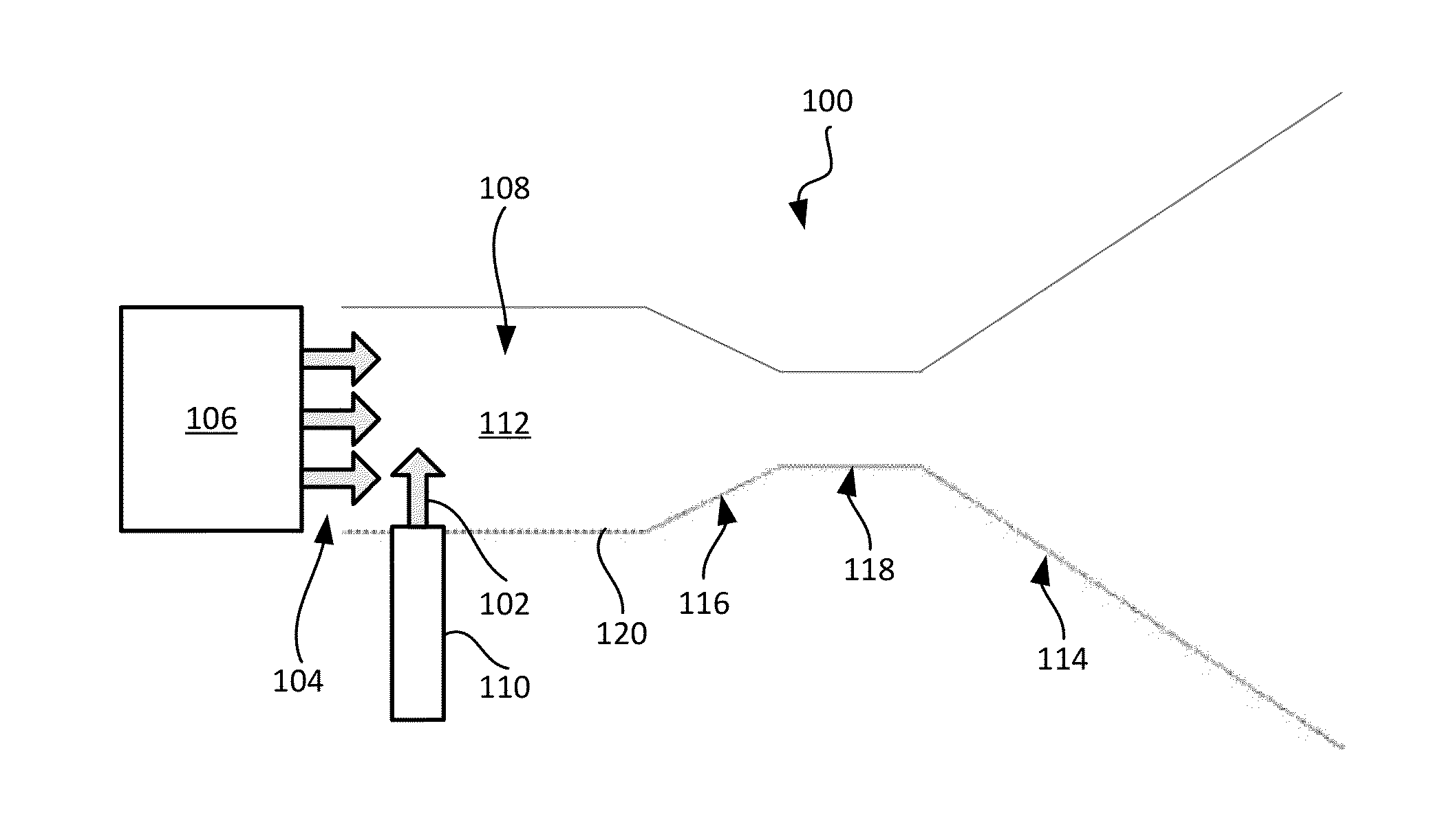
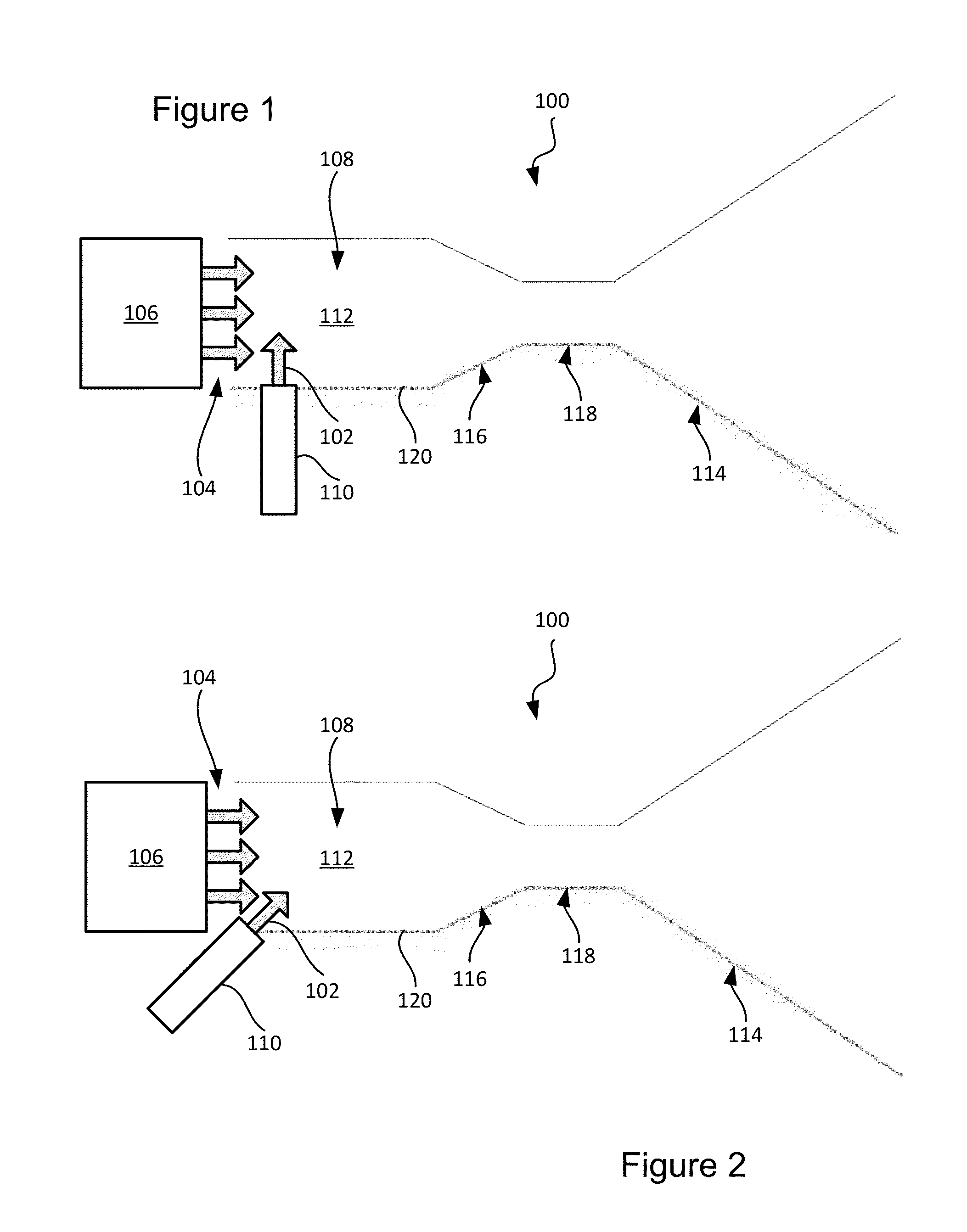
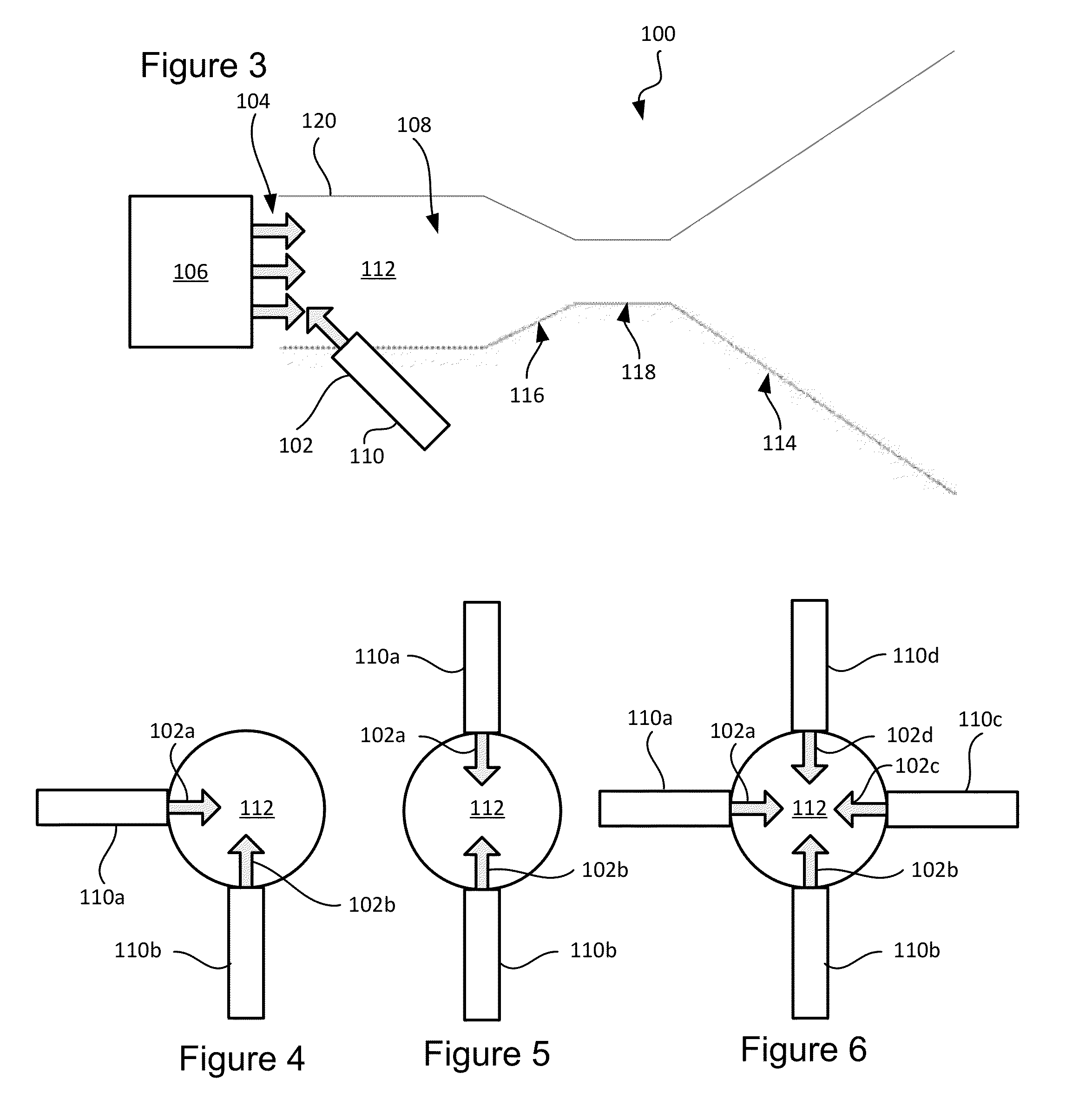
[0037]In some aspects of the subject technology, reactants can be reacted to produce byproducts by spraying the reactants into a plasma flow field in a react...


PUM


Abstract

Specific impulse and rocket engine efficiency can be improved by injecting reactants, e.g., a propellant combination or a monopropellant and a catalyst, into a plasma flow of a rocket engine. In some aspects, a catalyst or a propellant is carried by plasma formed by passing a flow of a feed gas through an electrical arc. In some aspects, reactants are combusted in supersonic plasma flow to generate combustion ionization in the plasma flow.

Description

CROSS-REFERENCE TO RELATED APPLICATION[0001]This application claims the priority benefit of U.S. Provisional Patent Application No. 61 / 805,837, filed Mar. 27, 2013, titled PLASMA SPRAYED CATALYST FOR ROCKET PROPULSION, the entirety of which is incorporated by reference herein.STATEMENT REGARDING FEDERALLY SPONSORED RESEARCH OR DEVELOPMENT[0002]Not applicable.FIELD OF THE INVENTION[0003]The present invention generally relates to rocket engines, including, for example, engines for catalyst-activated propellant and bipropellants engines.BACKGROUND[0004]Traditional propulsion systems for catalyst-activated propellants pass a monopropellant through a fine-mesh screen or other fixed element coated with a catalyst that initiates an exothermic reaction that disassociates the propellant into one or more high temperature products that are expelled through a nozzle. An example engine may use hydrazine as the monopropellant and iridium as the catalyst, wherein the decomposition produces a 1000°...

Claims


Application Information

Patent Timeline
Patent Type & Authority Applications(United States)
IPC IPC(8): F02K9/50
CPCF02K9/50F03H1/00B64G1/415F03H1/0006F03H1/0081F03H1/0093F03H1/0087F03H1/0012F03H1/0025F02K9/52F02K9/44F02K9/42F02K9/94F02K9/26F02K9/68F02K9/95F02K9/82F02K9/60
Inventor KNAUER, LARRY D.PIERSON, EDWARD A.KHAYMS, VADIM
Owner LOCKHEED MARTIN CORP
Why Eureka
Try Eureka