Reactor

a technology of reactors and reactors, applied in the field of reactors, can solve the problems of requiring laborious reactor transport, affecting the efficiency of the reactor, and the risk of contamination during fermentation is particularly critical, and achieves the effects of simple gas distribution, good mixing, and effective surface gas introduction

Inactive Publication Date: 2014-10-02
BAYER INTELLECTUAL PROPERTY GMBH
View PDF3 Cites 4 Cited by
  • Summary
  • Abstract
  • Description
  • Claims
  • Application Information

AI Technical Summary

Benefits of technology

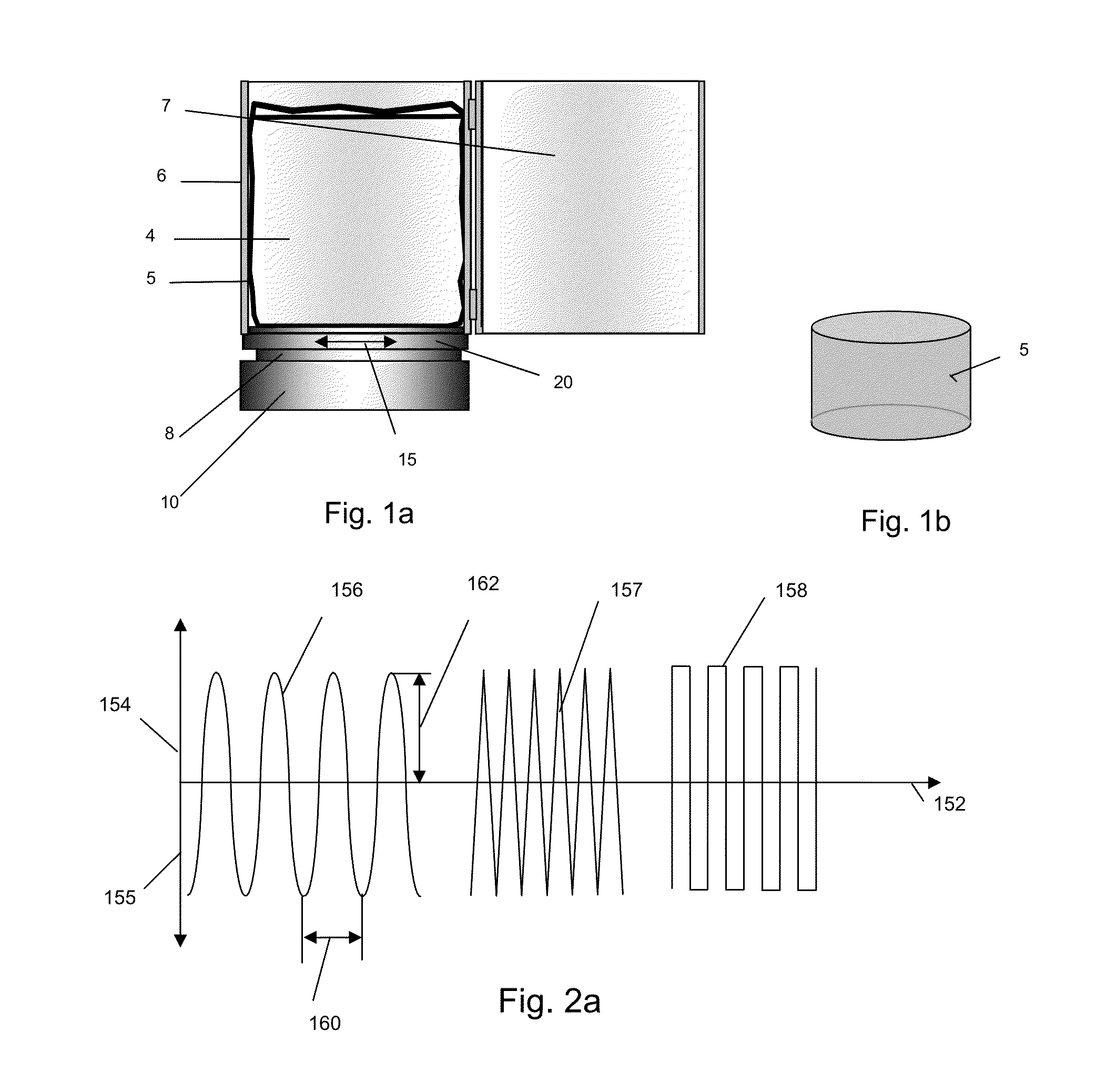
[0030]The reactor has, in particular, a ratio of height to mean diameter of 0.2-2.0, preferably 0.6-1.2 and particularly preferably 0.8-1.0. As a result, tilting moments caused, e.g. by unbalanced masses, can be reduced and a possibility of operation from above is ensured, despite an erection space requirement which can be achieved without problem even on a large scale. In contrast to the slim reactors introduced in biotechnology, such a broad reactor design offers the possibility of dispensing with accommodating reactors in expensive high-rise buildings in favor of erection in cheaper shed-shaped facilities.
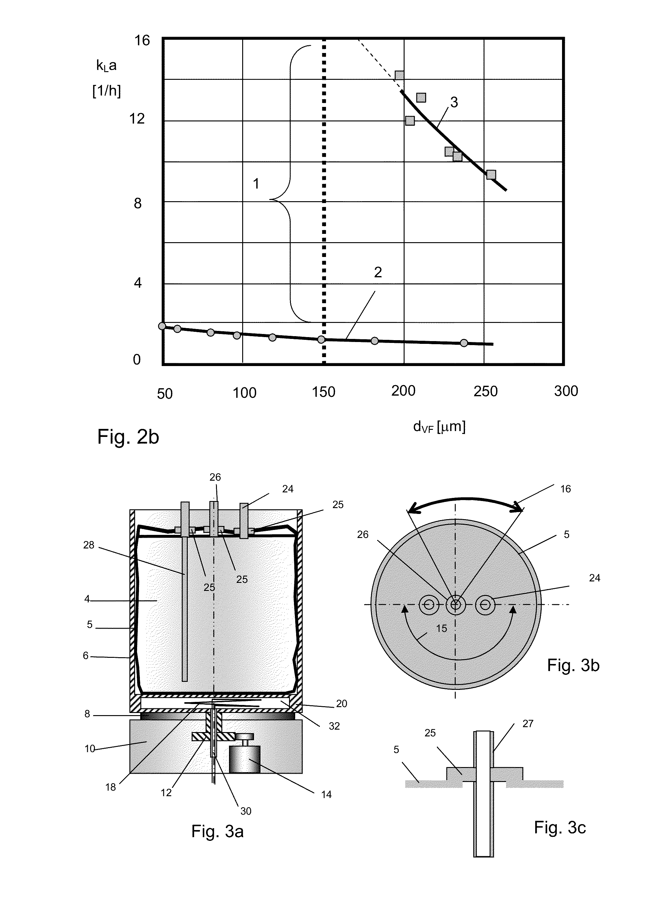
[0050]In a preferred embodiment, the reactor vessel has an elongate fluorescence sensor running essentially in the peripheral direction to the axis of the reactor, using which, in particular a pH and / or an oxygen concentration of the reactor contents can be detected. For contact-free detection, an optical detection apparatus at a distance from the reactor vessel is provided, which gives off, for example, a light flash, in order to be able to determine, from the reaction of the fluorescence sensor to the light flash, the desired measured value. In particular, the detection rates and the oscillatory-rotary motion are selected in such a manner that the fluorescence sensor is optically detected at various part-surfaces. It is therefore possible to irradiate the fluorescence sensor at different points, so that bleaching of the fluorescence sensor by “photo bleaching” is prevented and the service life is significantly increased.

Problems solved by technology

In order in the case of continuous process procedure to ensure sufficient long-term sterility, the autoclave technique is also used, which however, requires laborious transport of the reactors to the autoclave and is only usable with comparatively small reactor scales.
The risk of contamination during fermentation is particularly critical during sampling and at moving stirrer shafts.
This condition, especially in freezing and thawing processes, leads to considerably increased process times with increasing reactor scale, since no mixing elements can be used in these steps.
Heat transport into the reaction medium is limited by the thermal conductivity of the ice layer and also by free convection in the liquid.
Long process times, however, can lead to considerable product losses in the presence of proteolytic activity.
A great problem is the depth of penetration of the UVC radiation, which is frequently restricted to only a few tenths of a millimeter in biological media.
These membrane gas-introduction systems, however, are distinguished in that they can only be converted to an industrially relevant scale with limitations.
In the case of sparging, foaming problems can make the use, and the subsequent complex removal, of antifoams necessary in the DSP.
The cell stress on bubble rise, in the bursting of the gas bubbles at the surface, and in particular in the foamed destruction, is problematic in cell culture systems, since the cells can be permanently damaged by the resultant high shear forces which are introduced.
The damaged cells release proteins, the removal of which can lead to considerable product losses during workup.
The restricted cell density ultimately reduces the space-time yield of the fermenters and the capacity of the total plant.
Since a precondition for reliable upscaling in most cases is not considered technically as met, in the sparged single-use reactors, the volume enlargement must be achieved by complex paralleling of the systems.
If the fermenters are operated as proposed using standard agitating systems, although the volume which can be processed increases into the range of the permanently installed plants, the risk of contamination can only be managed with comparable technical expenditure, for example by the use of damped sliding-ring seals.
The great technical complexity and expenditure on personnel of such installations, however, largely emphasizes the advantages of the single-use concept.
Although this technology provides a gentle gas-introduction mechanism, it is restricted in conversion to an industrial scale.
Upscaling can therefore only be achieved via technically complex paralleling.
In both cases there is no possibility of agitating the product during the freezing process, which considerably lengthens the cooling and freezing processes.
The metal vessels are expensive and require large storage areas in the temporary storage.
The procedure of cutting them open is labor-consuming and contributes to fouling of the working environment.
The thawing process is time-intensive, because the ice blocks which float on the surface are hardly reached by the hydrodynamics prevailing in the reactor.
Product losses in the course of the long thawing phases are therefore unavoidable.
In the employment of all of the reactors listed here, considerable losses must be accepted in performance and upscalability.
In many cases, without sufficient scalability, apart from the lack of performance, an economic benefit cannot be guaranteed.
Scaleup here can only be achieved at the cost of increasing complexity and decreasing the economic benefit, such as, for example, by paralleling a plurality of reactors or by the additional use of technically complex solutions (for example sliding-ring seals built into the plastic bags).

Method used


Image

  • Reactor
  • Reactor
  • Reactor

Examples


Embodiment Construction

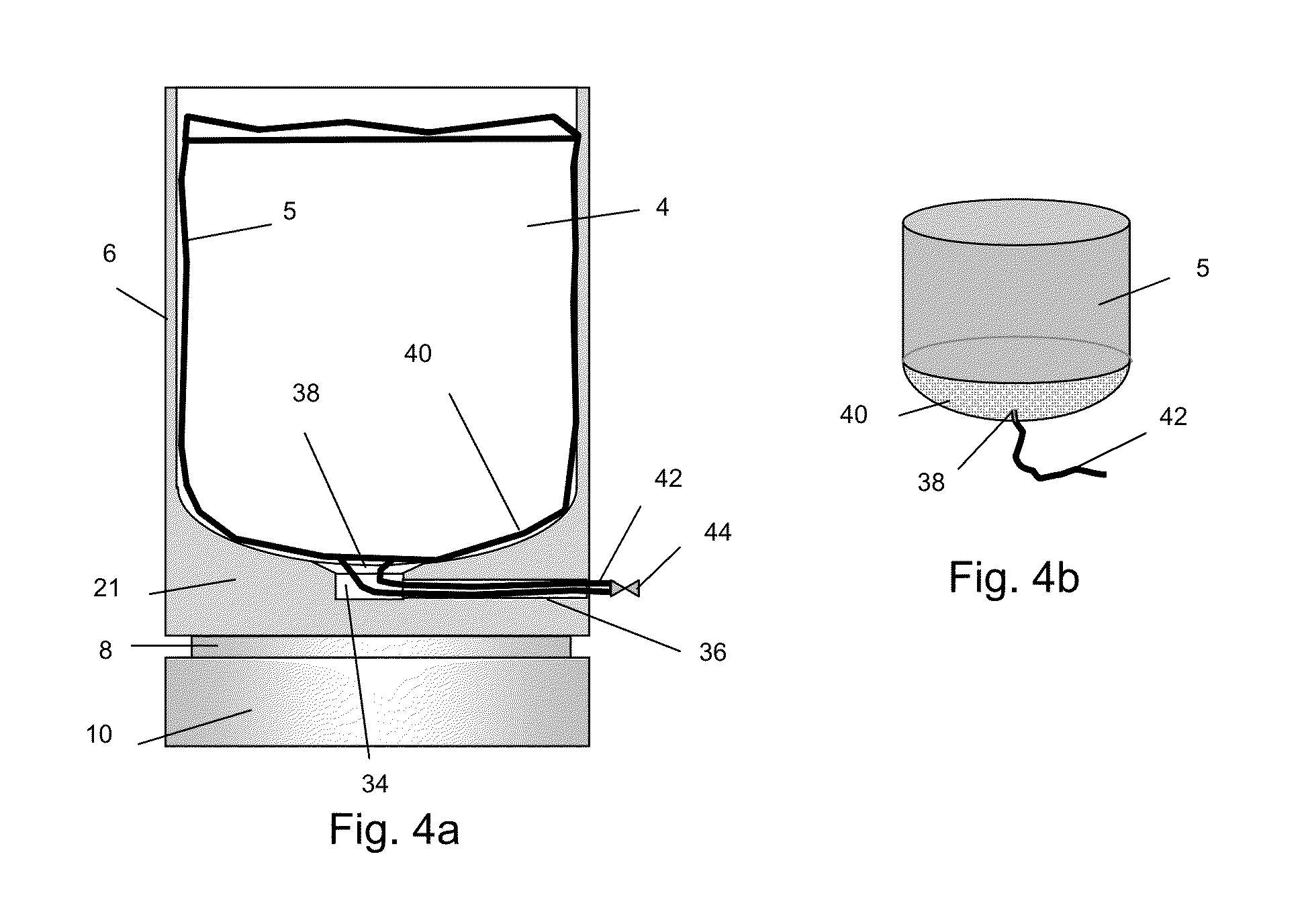
[0028]By means of the internals, distribution processes and / or mixing reactions can be carried out in a simple manner and with the same intensity as in a conventional stirred tank. In this design, a shaft passage can be dispensed with completely. The internals again may be supplied with material streams or energy streams via the side facing away from the product, which streams are introduced into the medium or discharged therefrom by diffusion, convection, heat conduction and / or radiation. In this manner, for the first time, in addition to mixing, numerous process engineering unit operations such as gas distribution, oxygen input by means of membrane gas introduction, heat transport, irradiation and / or particle retention can be carried out in a single-use reactor in a gentle manner and with an efficiency comparable to a stirred tank. The reactions and transport processes proceed in this case directly at the internals. Therefore, the sites of the greatest hydrodynamic energy density ...


PUM

PropertyMeasurementUnit
wavelengthaaaaaaaaaa
volumeaaaaaaaaaa
volumeaaaaaaaaaa

Abstract

The invention relates to a reactor driven in an oscillatory-rotary manner about its fixed, preferably vertical, axis, for preferably biotechnological and pharmaceutical applications. By means of its process-intensifying properties for mixing, suspension, gaseous material transport, heat transfer, irradiation and particle retention, the applicability on the industrial scale is ensured. The reactor which succeeds without a shaft seal permits particularly robust production with respect to sterile technique with avoidance of cleaning and cleaning validation required when the reactor is constructed as a single-use reactor.

Description

[0001]This is a Division of application Ser. No. 14 / 047,531 filed Oct. 7, 2013, which is a Division of application Ser. No. 12 / 297,987 filed Nov. 26, 2008, now U.S. Pat. No. 8,602,636, which is a 371 of PCT / EP2007 / 003521 filed Apr. 23, 2007, claiming priority of German Applicaton DE 10 2006 018 824.1 filed Apr. 22, 2006, the disclosures of which are all incorporated herein by reference.BACKGROUND OF THE INVENTION[0002]The invention relates to a reactor which is driven in an oscillating-rotating manner about a fixed vertical axis for biotechnological and pharmaceutical applications having process-intensifying properties for mixing, suspension, oxygen transport, heat transfer, irradiation and particle retention, which can be used, without shaft sealing, preferably as a disposable reactor, and thereby ensures a maximum level of process security in terms of cleaning and sterility.[0003]In the highly regulated production of pharmaceuticals, a large expenditure in terms of time, equipment...

Claims


Application Information

Patent Timeline
Patent Type & Authority Applications(United States)
IPC IPC(8): B01J19/28B01F11/00
CPCB01F3/04269B01J2219/00761B01F13/0018B01F13/0032B01F15/00733B01F15/0085B01F15/00915B01F15/065B01F15/066B01F2003/04361B01J19/28B01J19/285B01J2219/0025B01J2219/185B01J2219/192C12M23/14C12M27/02C12M27/10B01J19/123C12M23/28B01F11/0008B01F11/0002B01F23/23124B01F23/231231B01F31/10B01F33/501B01F33/5013B01F35/42B01F35/513B01F35/55B01F35/93B01F35/92B01F27/80B01F31/00B01F31/201
Inventor KAULING, JORGBROD, HELMUTSCHMIDT, SEBASTIANPOGGEL, MARTINFRAHM, BJORNROSE, REINHOLD
Owner BAYER INTELLECTUAL PROPERTY GMBH
Why Eureka
Try Eureka