
Anaerobic Digestion System

a technology of anaerobic digestion and anaerobic digestion, which is applied in the direction of waste based fuel, biochemistry equipment and processes, biochemistry apparatus, etc., can solve the problems of high electricity consumption and heavy maintenance, inability to process materials with a low porosity, and inability to achieve low porosity. , to achieve the effect of facilitating the internal circulation

Inactive Publication Date: 2014-10-16
CASTELLI LUIGI
View PDF8 Cites 3 Cited by
  • Summary
  • Abstract
  • Description
  • Claims
  • Application Information

AI Technical Summary

Benefits of technology

The patent describes a system for processing materials using cylindrical digesters that are shaped like cylinders and are fixed to the walls of a tank. Another embodiment of the system allows the digesters to float in the tank without being constrained in their vertical movement. This results in a lighter structure for the digester and reduces loads on it during loading and unloading phases. The system is designed to handle high-dry matter content materials and can be easily loaded using a fork lift or tractor. The heating of the liquid in the tank can be provided by biogas or solar radiation. The system includes containers for the inoculation liquid, animal waste water, and percolate and discharged liquid, as well as pumps, valves, and piping to convey the liquid to and from the digester. The system is designed to prevent the introduction of oxygen into the digester and allows for easy inspection and cleaning. The tank also contains floating elements to limit heat loss and reduce heat loss through the free surface of the liquid.

Problems solved by technology

The system described in EP 0476217 is provided with an agitation system for the treated material, which, in addition to being very complex from the construction point of view, has high electricity consumption and requires heavy maintenance.
These problems are present also in the system described in EP 0374708, which uses a rotating internal auger to move the material toward the outlet of the digester.
It is evident that the heat transfer through the walls of the “garage” is not very efficiency due to the poor contact.
Another disadvantage of this system is its inability to process material with a low porosity.
This system has operational problems and difficulties during the phase of replacing the material to be treated.
This type of system is not designed for anaerobic digestion; in fact it is provided with ducts for the entrance of the air required by the composting process.
In addition the rotation system is complex and expensive, which heavily impacts on the construction and amortisation costs.
Even more complex and onerous from the construction and operation points of view is the system described in U.S. Pat. No. 5,427,947, which includes a rotating cylindrical reactor for composting.

Method used


Image

  • Anaerobic Digestion System
  • Anaerobic Digestion System
  • Anaerobic Digestion System

Examples


Embodiment Construction

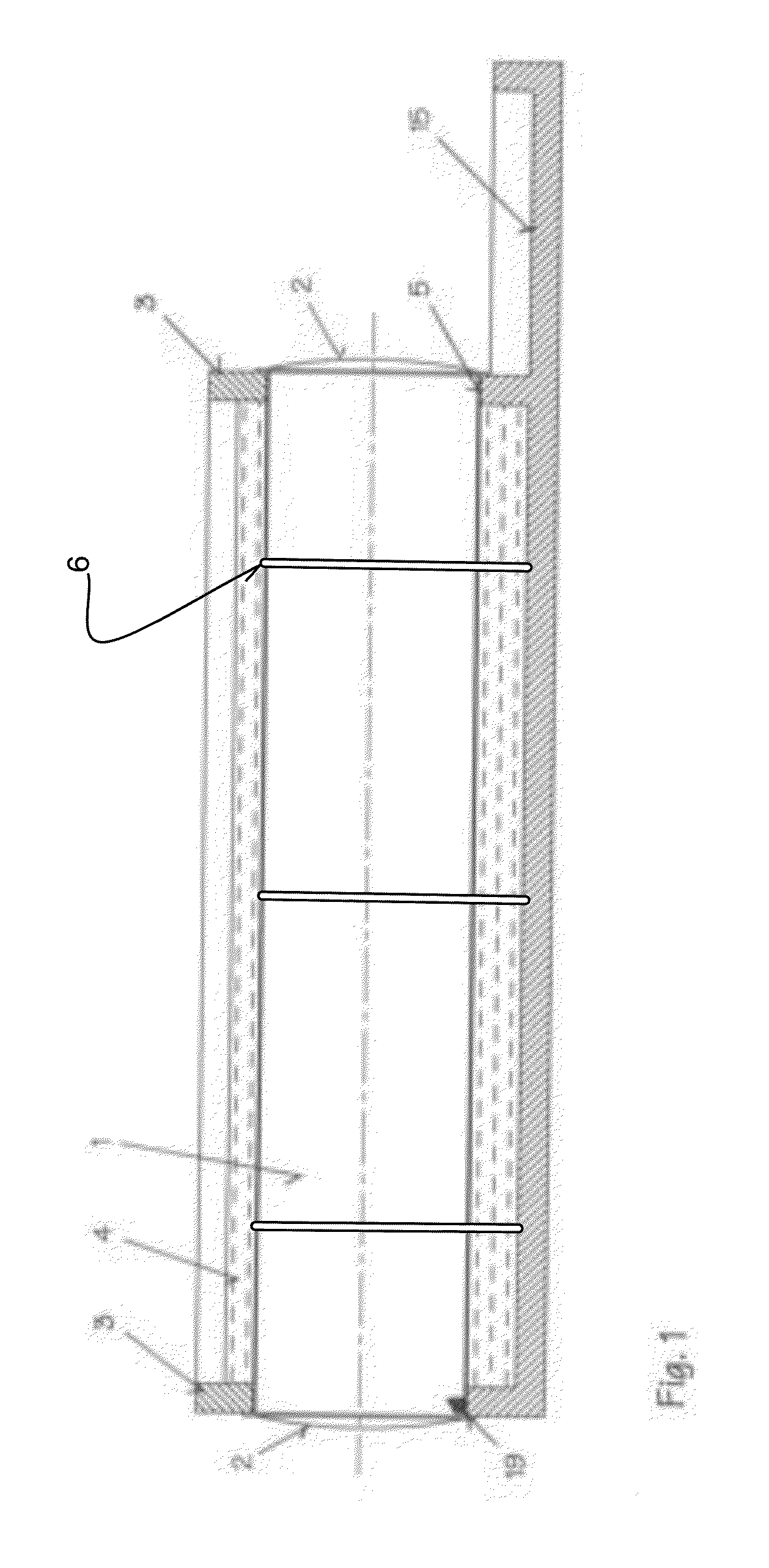
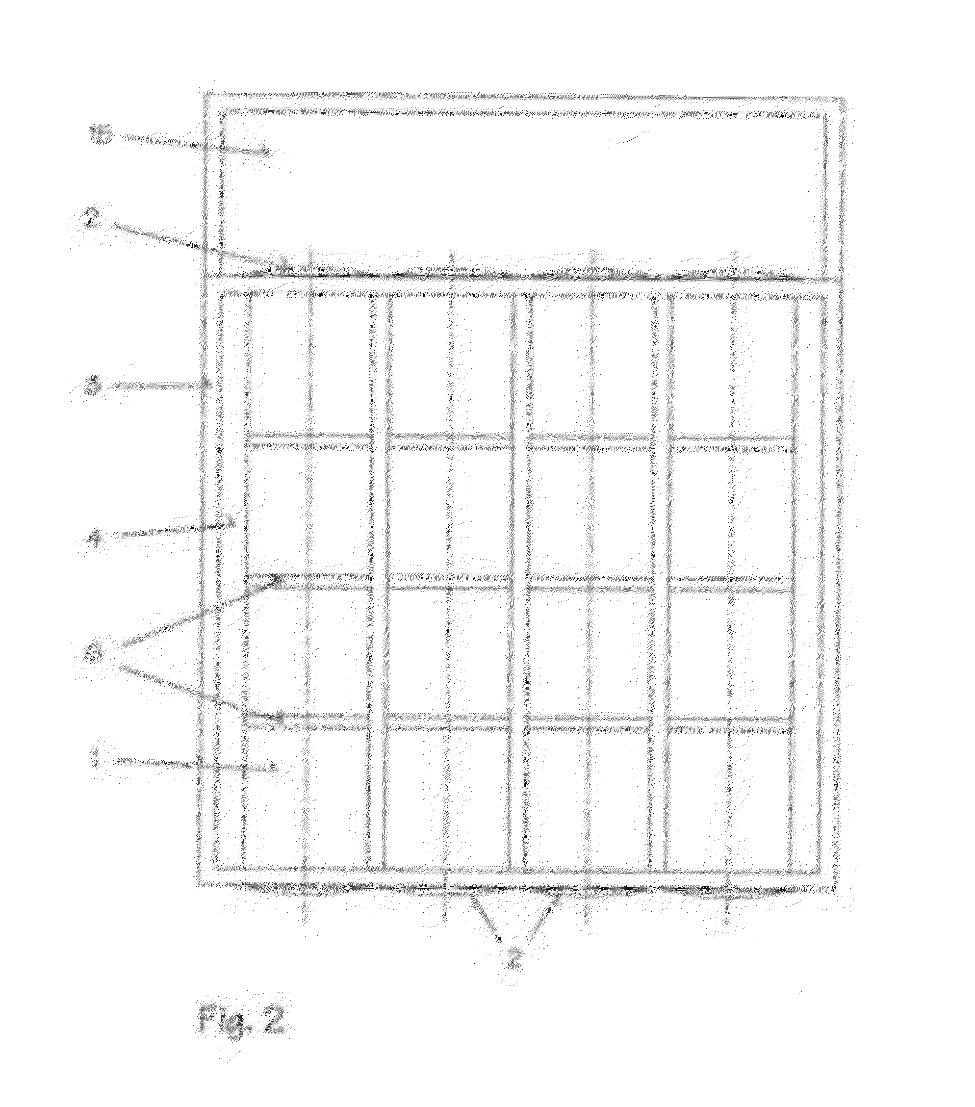
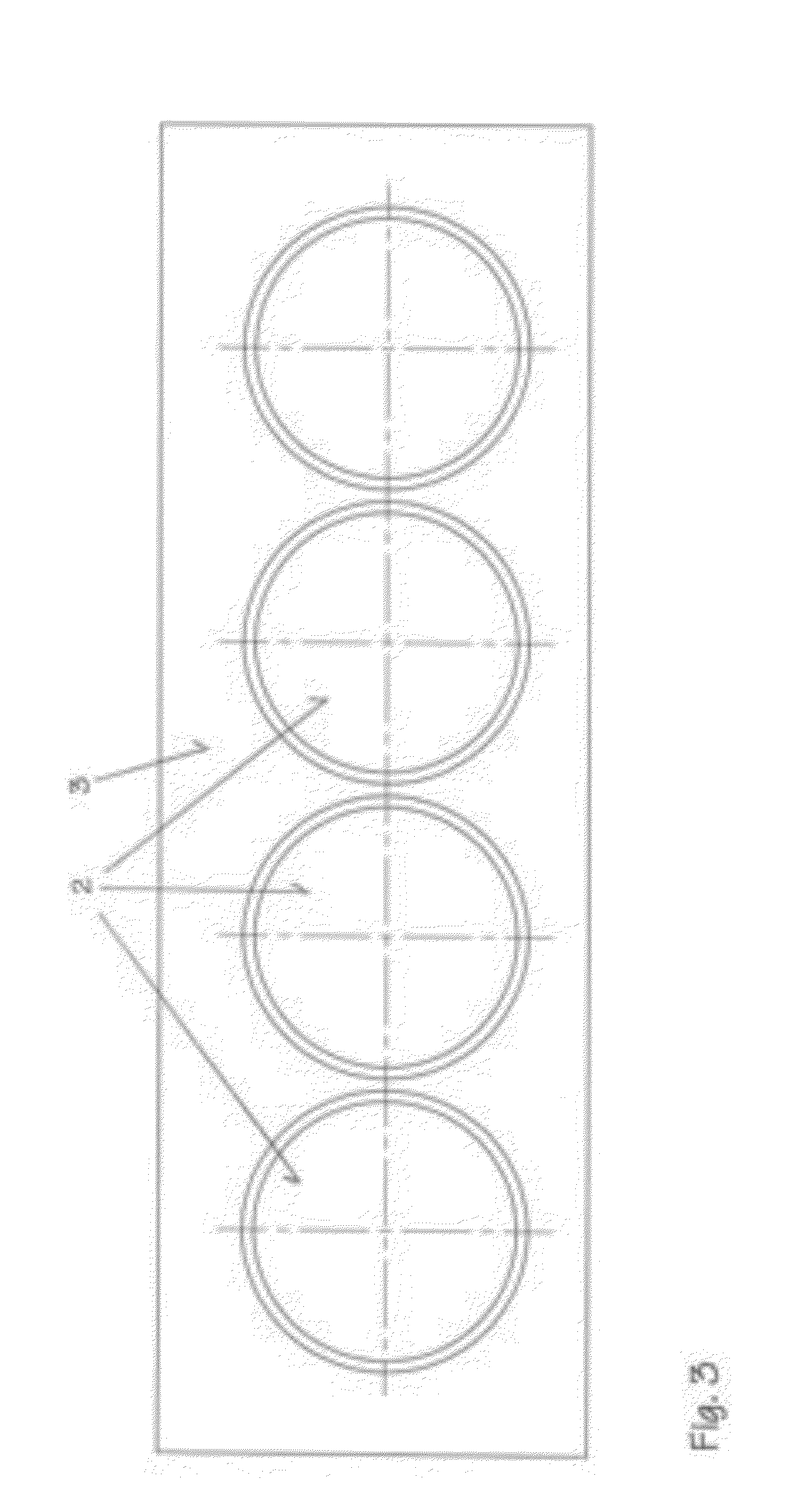
[0050]As it can be seen in the attached figures, this invention is relative to a new modular system of anaerobic digestion, substantially characterised by one or more horizontal digesters immersed in a heated liquid. In the first example shown in FIGS. 1-3, four parallel digesters are installed side by side. Each digester consists substantially of a cylindrical container 1, with its two ends closed by detachable covers 2, which is fixed to the two opposite walls of the tank 3 containing the heated liquid 4. The digester is gas and water-tight and it is provided with adequate seals 5 built during the construction phase to prevent the leakage of the liquid from the tank. In addition, these digesters, being immersed in the liquid, are subject to buoyancy, particularly when they are empty or during the filling phase, thus various tension rods 6 encircle the lateral surface of the digester and are anchored to the tank floor. In another embodiment not shown the digesters are parallelepipe...


PUM

PropertyMeasurementUnit
temperatureaaaaaaaaaa
shapeaaaaaaaaaa

Abstract

An anaerobic digestion system for digestion of animal or other organic material and production of biogas is shown. The digestion system includes a simplified construction and improved agitation system both partially enabled by a dual container system that makes use of the buoyancy of the digestion container for support.

Description

CROSS-REFERENCE TO RELATED APPLICATIONS[0001]This application claims priority to U.S. Provisional application No. 61 / 812,294 titled: Anaerobic Digestion System for Production of Biogas from Agricultural Biomass, Animal Manure and Waste Water and Organic Solid Waste, filed on 16 Apr. 2013 by the same inventor and currently pending.BACKGROUND OF THE INVENTION[0002]1. Technical Field[0003]This invention is relative to an anaerobic digestion system for the production of biogas from various organic matters, such as agricultural biomass, sludge and solid waste.[0004]2. Related Background Art[0005]The anaerobic treatment of biomass and wastes has recently become very important, because it generates energy without negative environmental impact. Biogas is a very valuable form of energy, because it contains methane, a combustible gas which during combustion produces two chemical compounds which are harmless for the environment: water and carbon dioxide from a renewable source.[0006]It is ther...

Claims


Application Information

Patent Timeline
Patent Type & Authority Applications(United States)
IPC IPC(8): C12P5/02
CPCC12P5/023C12M21/04C12M27/10Y02E50/30
Inventor CASTELLI, LUIGI
Owner CASTELLI LUIGI
Learn More