Method and light pulse source for generating soliton light pulses

a light pulse and soliton technology, applied in the field of soliton light pulse generation, can solve the problems of low damage threshold, difficulty in tuning the generated wavelength, and requirement of establishing phase matching, and achieve the effects of reducing the density of the operation medium, increasing the waveguide diameter, and low dispersion

Inactive Publication Date: 2014-11-13
MAX PLANCK GESELLSCHAFT ZUR FOERDERUNG DER WISSENSCHAFTEN EV
View PDF1 Cites 20 Cited by
  • Summary
  • Abstract
  • Description
  • Claims
  • Application Information

AI Technical Summary

Benefits of technology

[0060]As a further advantage of the invention, multiple variants of creating the fundamental soliton light pulses in the pulse guiding medium are available, which can be provided separately or in combination. With a first variant, at least one of the pump laser pulse energy, the pump laser pulse center wavelength and the pump laser pulse duration can be adjusted. With a second variant, a particular pulse guiding medium can be selected, which has a predetermined nonlinearity, a predetermined group velocity dispersion and/or a predetermined ionization threshold.
[0061]According to a particularly preferred embodiment of the invention, the pulse guiding medium comprises a hollow optical waveguide device containing an ionisable gaseous, vaporized or liquid or liquid waveguide medium. The hollow optical waveguide device generally comprises an optical waveguide with a longitudinal extension for propagating the light pulses. The waveguide includes a core which is filled with a waveguide medium. The optical features of the pulse guiding medium are defined by the superimposed optical features of the waveguide material as such and the waveguide medium. The waveguide medium can be a gas, a vapour or a liquid, having the following features. The refractive index of the waveguide medium preferably is not interspersed with resonances in the spectral region of interest. The refractive index varies (grows) smoothly with frequency in the given frequency range. Furthermore, the group velocity dispersion contribution of the waveguide medium for a given pressure does not outweigh the waveguide contribution in such a way that the total dispersion becomes normal. In other words, the anomalous dispersion is kept in the waveguide medium. Finally, the waveguide medium does not suffer permanent damage due to the photoionization used for frequency-shifting. For providing these features, the waveguide medium preferably comprises a gas, particularly preferred a noble gas, such as Ar, Ne or Xe, or other gases, such as H2, O2, N2, or gaseous SF6, or a vapour, such as Rb or Cs. Alternatively, a liquid with a low mass density could be used, such as liquid argon.
[0062]With a particularly advantageous embodiment of the invention, the hollow optical waveguide device comprises a photonic-crystal fiber (PCF). The use of a PCF for simultaneous compression and frequency up-conversion of fundamental solitonpulses represents an independent subject of the present invention. Preferably, the PCF comprises a Kagomé fiber, a hypocycloid fiber or a square lattice fiber. PCF's have particular advantages in terms of accommodating selected waveguide media, adjusting the GVD and Kerr-nonlinearity and adjusting an operation medium density. The PCF has a hollow core, which preferably has a diameter below 150 μm. Alternatively, larger waveguide diameters can be used. Increasing the waveguide diameter may have advantages resulting from a possible reduction of the operation medium density in the waveguide. Thus, with an alternative embodiment of the invention, the hollow optical wav

Problems solved by technology

Limitations of this technique are: the difficulty in tuning the generated wavelength (usually determined by the wavelength of the pump field), the low damage threshold that prevents applications for high-energy pulses, and the requirement of establishing phase matching.
This causes low conversion efficiencies and narrow output spectra.
Furthermore, normal dispersion limits the intensity of the frequency shifted light pulses.
The drawbacks of this technique are the complexity of the setup, the regular need for realignment and the strongly modulated spectral amplitude that will lead to satellite pulses in the time domain.
Generally, conventional adiabatic soliton compression is limited to low soliton energies, which can propagate in compact fibers, and thus to particular appli

Method used


Image

  • Method and light pulse source for generating soliton light pulses
  • Method and light pulse source for generating soliton light pulses
  • Method and light pulse source for generating soliton light pulses

Examples


first embodiment

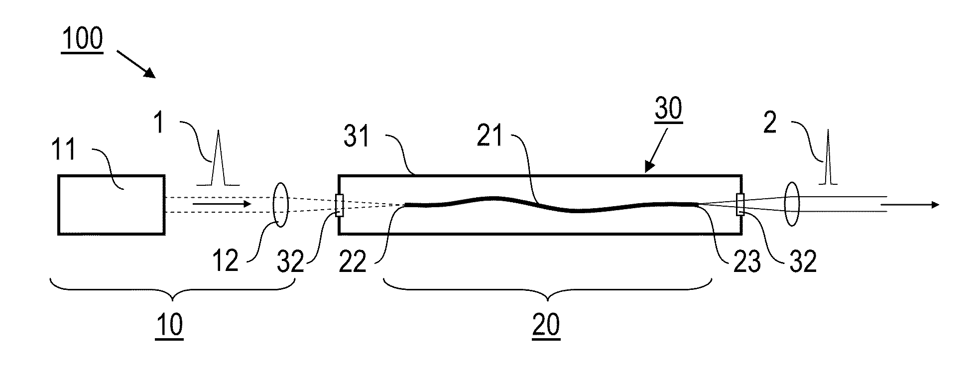
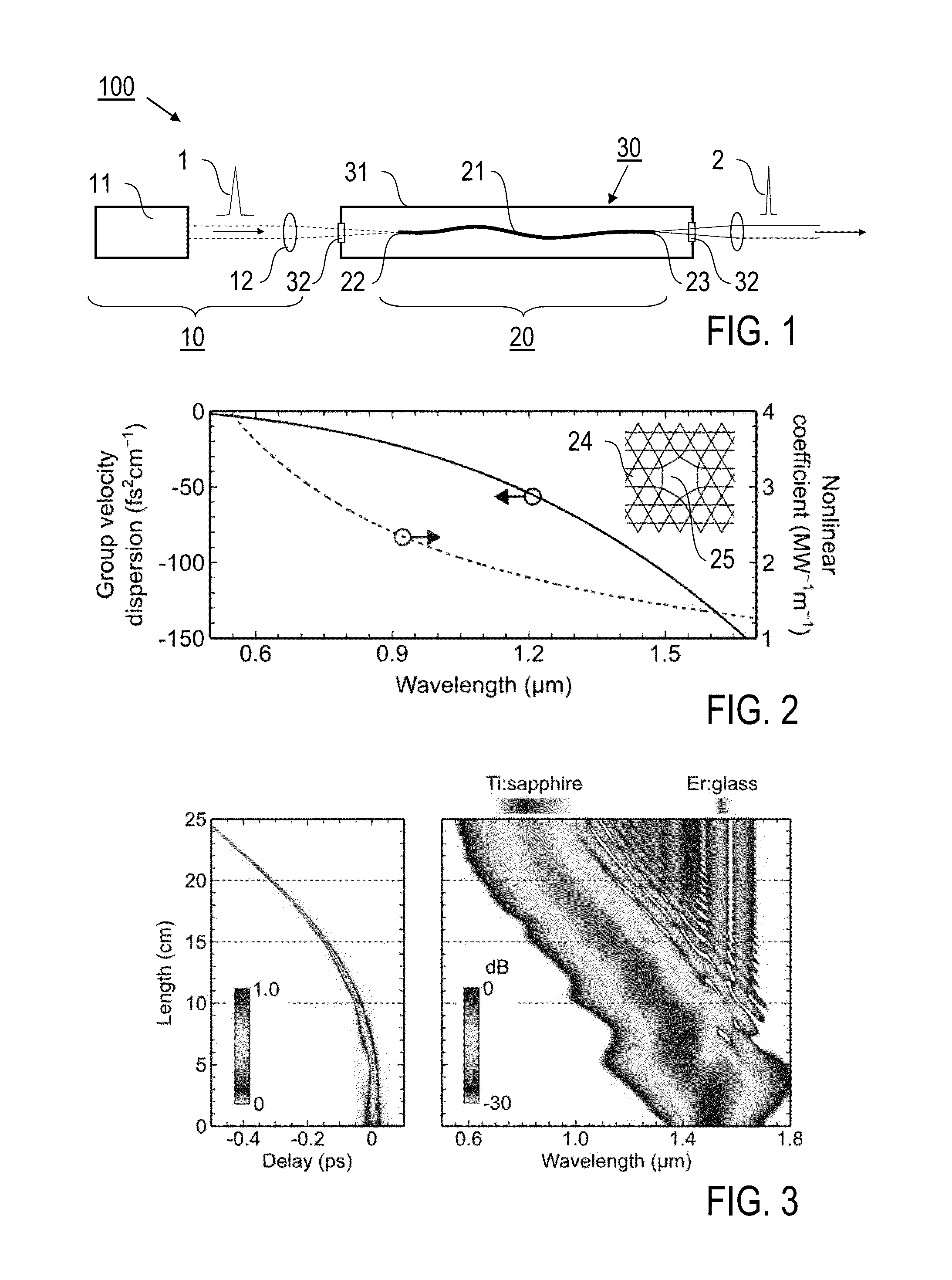
[0078]A first embodiment of a light pulse source device 100 according to the invention is schematically illustrated in FIG. 1. The light pulse source device 100 comprises a pump laser source 10 with a pulse laser 11 and focusing optics 12 and a pulse guiding medium 20 comprising a PCF 21 which is arranged in a pressure system 30 including at least one optically accessible gas cell 31. The pump laser 11 is e.g. an optical parametric amplifier (OPA) or a fiber laser. PCF 21 is a Kagomé-lattice hollow-core PCF which is made using the procedure and facilities as discussed in [6]. The PCF 21 has an inner hollow core 25 (see FIG. 2, insert) with a diameter of e.g. 18 μm. A piece of PCF 21 of the required length, e. g. 25 cm, is fitted into the gas cell 31, wherein a front facet 22 and a rear facet 23 of the PCF 21 are kept in place by using e.g. V-grooves. The shape of PCF 21 in the gas cell 31 can be straight or slightly curved (as shown). The gas cell 31 is optically accessible from bot...


PUM


Abstract

A method of generating light pulses including pumping laser pulses with a pump laser source, coupling the laser pulses into a pulse guiding medium having an anomalous group-velocity dispersion and a Kerr nonlinearity, and propagating the laser pulses along the pulse guiding medium, wherein soliton-shaped light pulses are formed from the laser pulses within the pulse guiding medium and, resulting from a photoionization of the pulse guiding medium by the light pulses, the light pulses are subjected to a frequency, wherein the method further includes setting the pump laser source and the pulse guiding medium such that the light pulses are fundamental soliton light pulses propagating in the pulse guiding medium, wherein the group-velocity dispersion of the pulse guiding medium being selected such that a ratio of the dispersion and the Kerr nonlinearity decreases with increasing frequency and the fundamental soliton light pulses are compressed with the frequency shift.

Description

FIELD OF THE INVENTION[0001]The present invention relates to a method of generating soliton light pulses, in particular using optical waveguides with non-linear optical properties. Furthermore, the present invention relates to a light pulse source device for generating soliton light pulses, in particular comprising a pump laser source and a gas-filled hollow optical waveguide device. Applications of the invention are available in the fields of e.g. biomedical imaging, metrology, spectroscopy and material processing.TECHNICAL BACKGROUND OF THE INVENTION[0002]In the present specification, reference is made to the following publications cited for illustrating prior art techniques, in particular conventional non-linear optics and techniques of generating soliton light pulses.[0003][1] Franken et al., Phys. Rev. Lett. 7, 118 (1961),[0004][2] Nisoli et al., Appl. Phys. Lett. 68, 2793 (1996),[0005][3] Mamyshev et al., Phys. Rev. Lett. 71, 73 (1993),[0006][4] Hölzer et al., Phys. Rev. Lett....

Claims


Application Information

Patent Timeline
IPC IPC(8): G02F1/35
CPCG02F1/3513H01S3/0057H01S3/1305
Inventor HOLZER, PHILIPPCHANG, WONKEUNTRAVERS, JOHNBIANCALANA, FABIORUSSELL, PHILIP
Owner MAX PLANCK GESELLSCHAFT ZUR FOERDERUNG DER WISSENSCHAFTEN EV
Why Eureka
Try Eureka