Chemical-looping combustion method with dilute phase removal of ashes and fines in the oxidationzone and plant using same

a combustion method and combustion technology, applied in the direction of combustion types, furnaces, lighting and heating apparatuses, etc., can solve the problems of ash formation, inability to provide a specific device for separation and discharge of ashes formed during combustion of solid feedstocks, and difficulty in estimating grain size of agglomerated ashes

Active Publication Date: 2014-11-13
TOTALENERGIES ONETECH +2
View PDF3 Cites 14 Cited by
  • Summary
  • Abstract
  • Description
  • Claims
  • Application Information

AI Technical Summary

Problems solved by technology

Another problem linked with chemical-looping combustion of solid feedstocks relates to the formation of ashes.
The grain size of the agglomerated ashes is more delicate to estimate and depends on the conditions of implementation of the method.
In this system, no specific device allowing separation and discharge of the ashes formed during combustion of the solid feedstocks is provided.
However, this means does not allow to control elutriation of the ashes and elutriation of the unburnt particles separately.
In fact, in this case, good elimination of the ashes produced is consecutively translated into a significant elimination of the unburnt particles and therefore a decrease in the energy efficiency or a decrease in the CO2 capture rate.
The accumulation of ashes has many consequences and it generates two major drawbacks:solid flow disturbance through modification of the average grain size of the bed likely to cause control problems as regards the circulation of this solid bed,dilution of the oxygen-carrying function of the metallic oxides, leading to a decrease in performance of the method.
The aforementioned bottom ash issue mainly concerns the reduction zone (fuel reactor).

Method used


Image

  • Chemical-looping combustion method with dilute phase removal of ashes and fines in the oxidationzone and plant using same
  • Chemical-looping combustion method with dilute phase removal of ashes and fines in the oxidationzone and plant using same
  • Chemical-looping combustion method with dilute phase removal of ashes and fines in the oxidationzone and plant using same

Examples


example

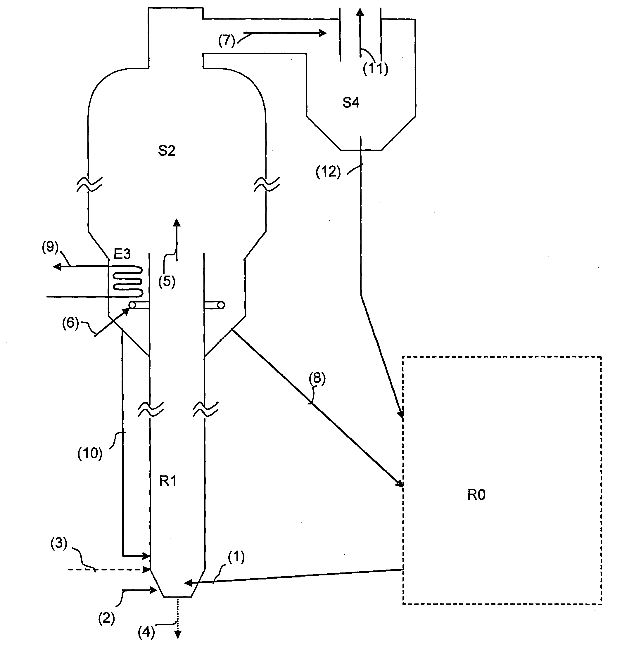
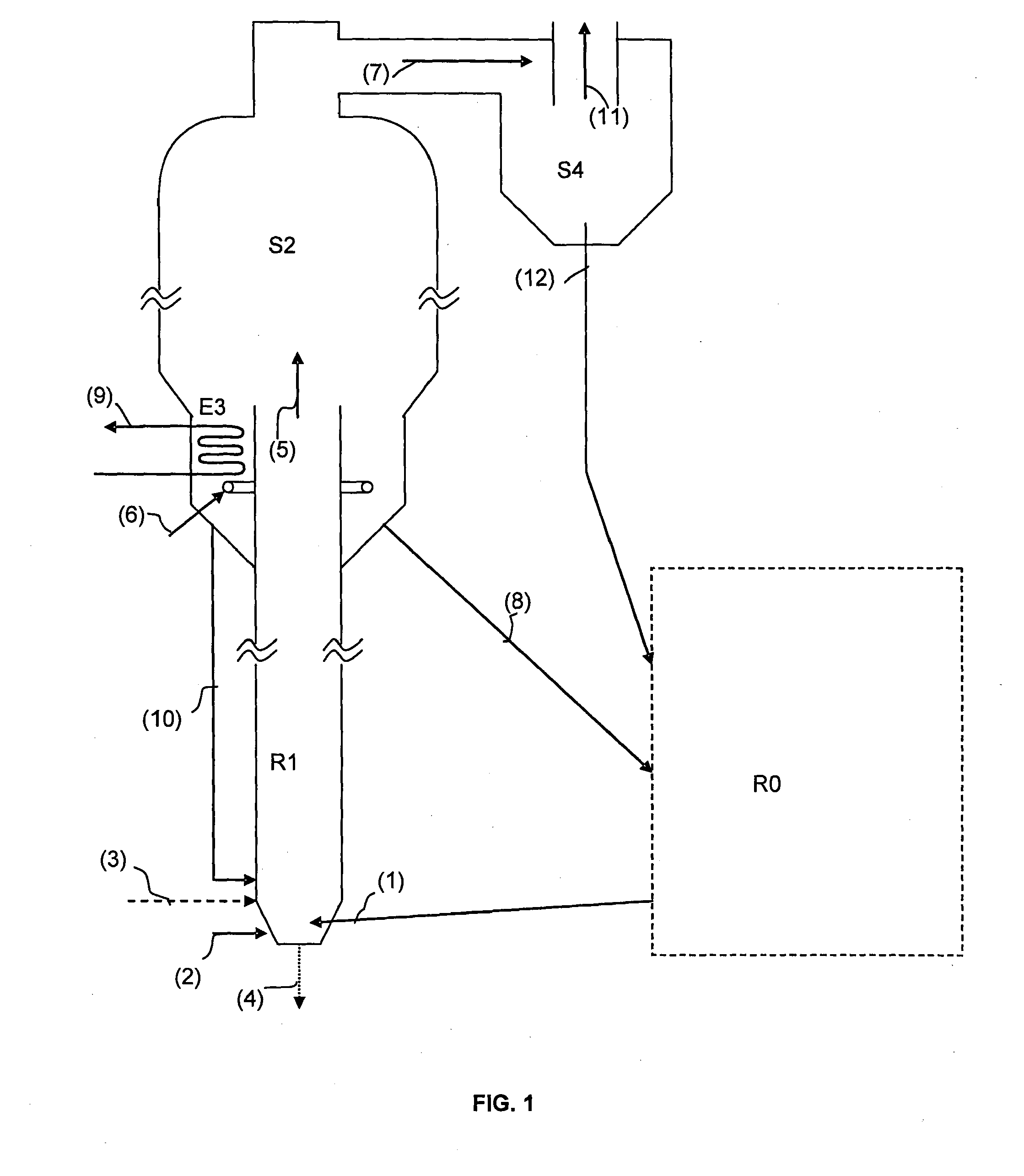
[0105]The example relates to FIG. 1.

[0106]We consider here a chemical loop wherein an oxygen-carrying metallic oxide circulates with a gross thermal power of the order of 300 MWth, i.e. a solid circulation equivalent to 1077 kg / s.

[0107]We consider the combustion of a gas containing 14% ashes feeding the unit at a rate of 11.6 kg / s. The coal is supplied in the fuel reactor with a grain size characterized by the fact that less than 2% of the coal has a particle size above 200 microns.

[0108]The oxygen carrier used is a solid of ilmenite type with a density of 5000 kg / m3.

[0109]The present example relates to the removal of ashes in the air reactor (oxidation zone) according to the present invention in such a way that the ashes removed are equivalent, in mass flow rate, to the flow of ashes entering the unit (corresponding to the ashes of the feedstock supply on a continuous basis), i.e. a flow of ashes to be removed of 1.62 kg / s. By hypothesis, the ashes are only removed at the level of ...


PUM


Abstract

The invention relates to a method for chemical-looping combustion of a hydrocarbon-containing feedstock, comprising:contacting oxygen-carrying material particles coming from a reduction zone R0 with an oxidizing gas stream in a reactive oxidation zone R1,separating the fly ashes, the fines and the oxygen-carrying material particles within a mixture coming from zone R1 in a dilute phase separation zone S2, the driving force required for dilute phase elutriation in S2 being provided by the oxidizing gas stream from reactive oxidation zone R1. Optionally, partitioning is carried out in a dedusting zone S4, then possibly in a dense phase elutriation separation zone S5. The invention also relates to a chemical-looping combustion plant allowing said method to be implemented.

Description

FIELD OF THE INVENTION[0001]The invention relates to the sphere of chemical-looping redox combustion of solid hydrocarbon-containing feedstocks in order to produce energy, syngas and / or hydrogen.[0002]More particularly, the invention relates to the removal of ashes and fines produced in the chemical-looping combustion plant.[0003]Terminology[0004]Chemical-Looping Combustion or CLC: In the text hereafter, what is referred to as a CLC (Chemical-Looping Combustion) is a loop oxidation-reduction (redox) process on active mass. It can be noted that, in general, the terms oxidation and reduction are used with regard to the oxidized or reduced state of the active mass respectively. In a chemical-looping combustion plant, the oxidation zone is where the redox mass is oxidized and the reduction zone is where the redox mass is reduced.[0005]Devolatilization[0006]During thermal treatment, the organic compounds lose volatiles, first water and carbon dioxide, liquid and then gaseous hydrocarbons...

Claims


Application Information

Patent Timeline
Patent Type & Authority Applications(United States)
IPC IPC(8): F23C10/01F23C10/24F23C10/08
CPCF23C10/01F23C10/08F23C10/24F23C10/005F23C10/26F23C2900/99008F23C2900/10003Y02E20/34
Inventor GUILLOU, FLORENTGAUTHIER, THIERRYHOTEIT, ALIRIFFLART, SEBASTIEN
Owner TOTALENERGIES ONETECH
Why Eureka
Try Eureka