
Image guided protocol for cell generation

a cell generation and image guided technology, applied in the field of image guided protocol for cell generation, can solve the problems of low yield of the protocol, markers themselves exhibit a great deal of variability, markers introduce additional cost, etc., to achieve high yield cell generation, avoid wasteful processing, and reduce the cost and labor of cell generation.

Active Publication Date: 2014-11-27
LEICA MICROSYSTEMS CMS GMBH
View PDF5 Cites 4 Cited by
  • Summary
  • Abstract
  • Description
  • Claims
  • Application Information

AI Technical Summary

Benefits of technology

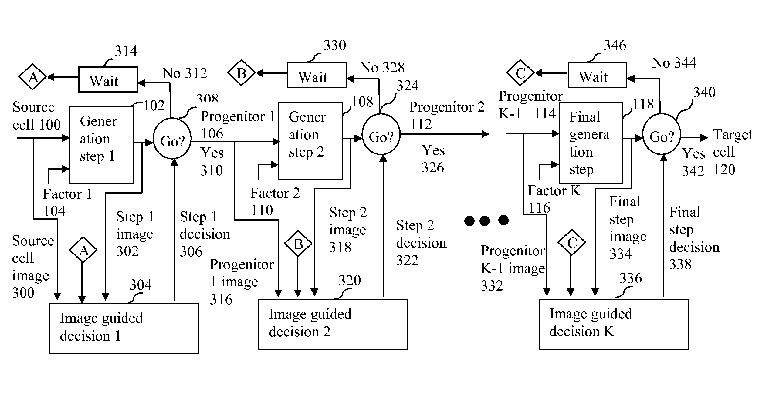
The invention provides a way to generate a high yield of cells using image guidance and dynamic control. It also includes a recovery step to fix any problems that might arise during the cell generation process. Additionally, the invention has a fail detection method to stop the process quickly and prevent wasted resources. The dynamic control method used in the invention doesn't require extensive markers, which reduces costs and labor.

Problems solved by technology

However, the yield of the protocols is low.
This is partially due to many challenges in the complex environment around the cell generation.
Key challenges for a cell generation protocol includeefficient induction of the correct germ layer;correct timing of activation or inhibition of various morphogenic pathways, especially given that the very same pathway can have a stimulatory or an inhibitory influence at different times;careful control of the concentration of the inducing factors.
However, the markers themselves exhibit a great deal of variability because there are significant variations among different cell lines, perhaps because individual lines may make variable amounts of their own inducing factors.
In addition, markers introduce additional cost and could have adverse side-effect such as toxicity to the cell generation protocol.
Therefore, quantification markers are not desirable in practical clinical laboratory settings.
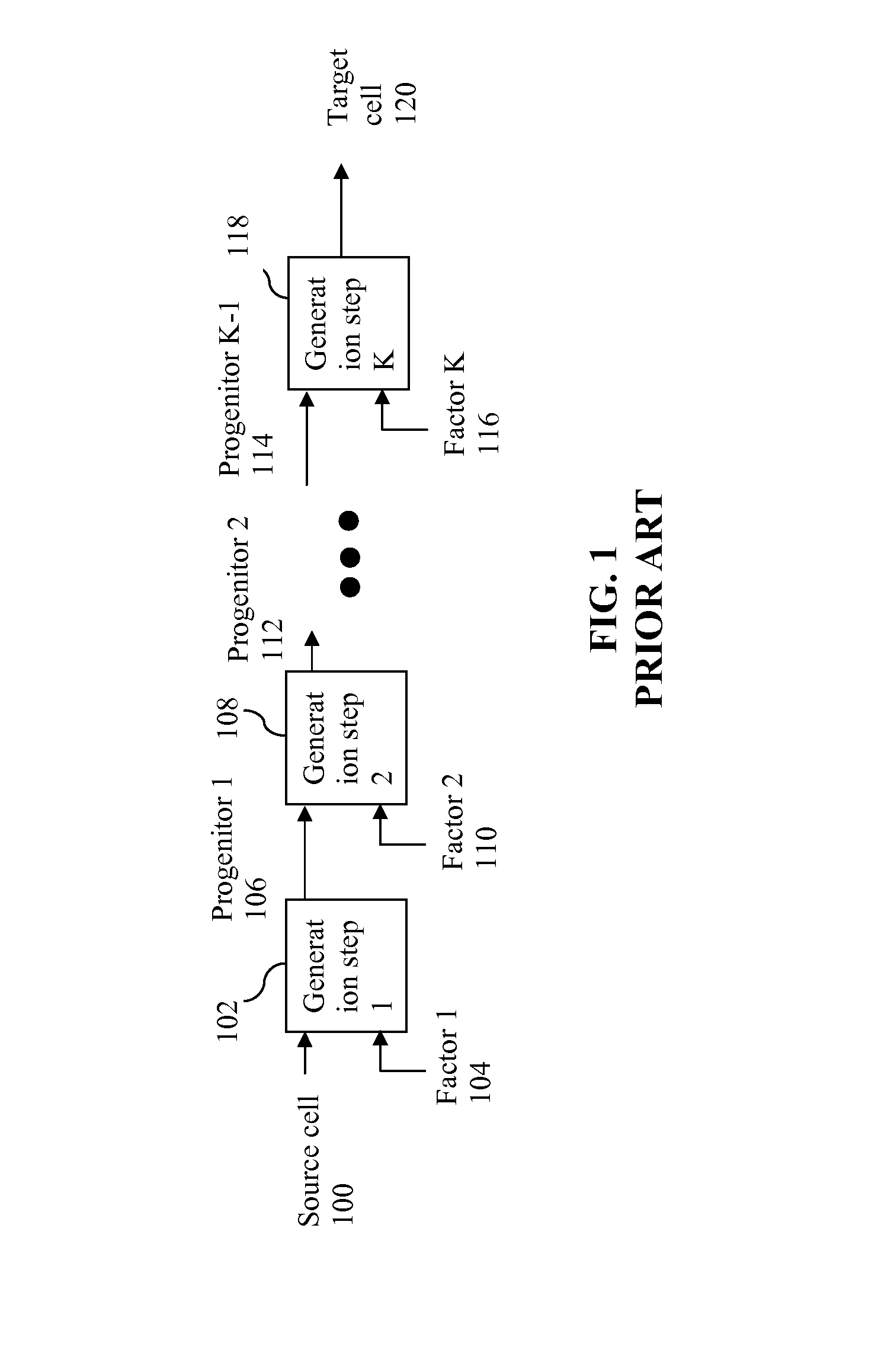
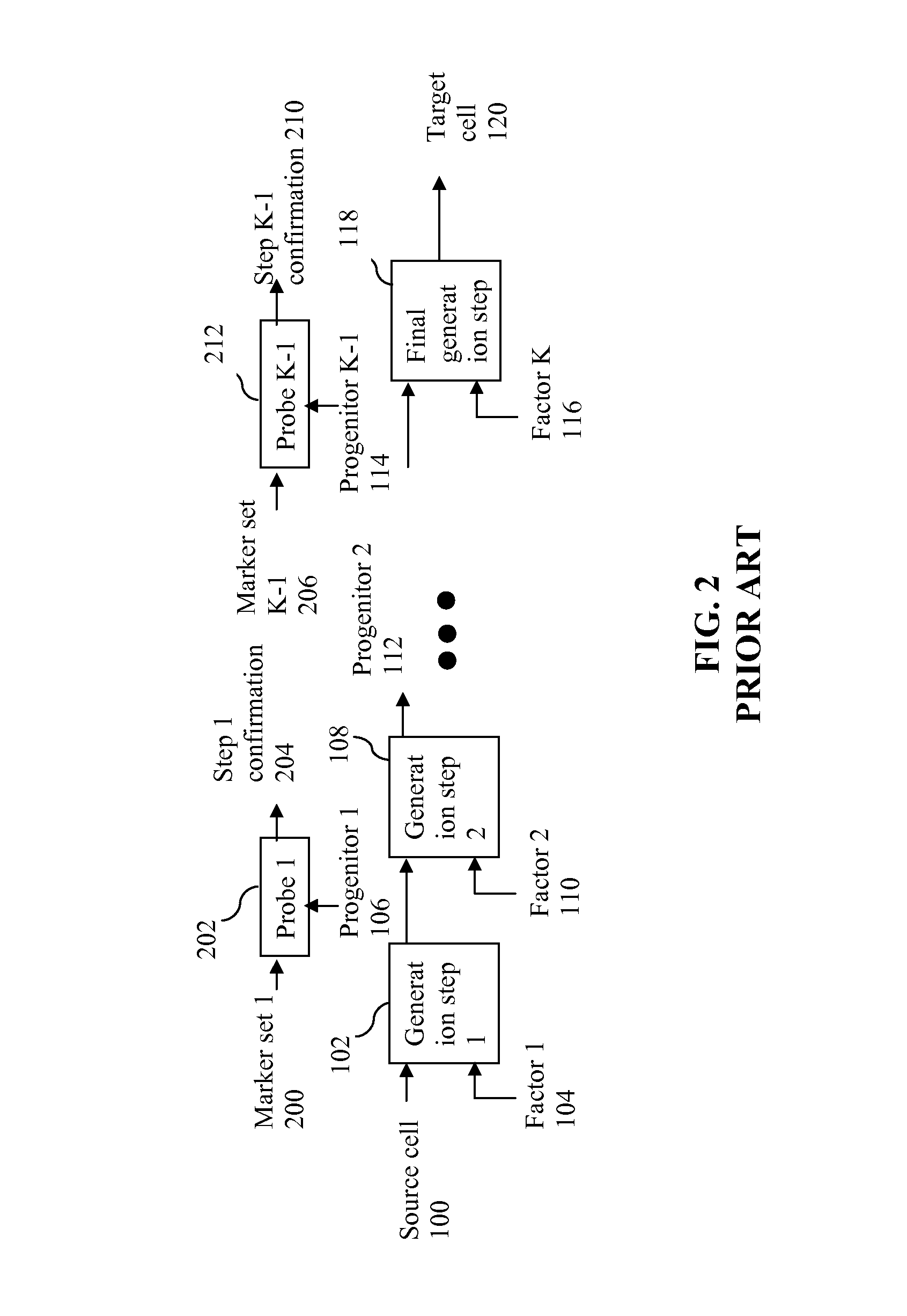
During the implementation of the protocol, only a limited number of simple markers could be used, especially for the mass production of patient-specific cells.
The low yield and the lack of adequate feedback during the protocol implementation represent a significant hurdle of production level cell generation.

Method used


Image

  • Image guided protocol for cell generation
  • Image guided protocol for cell generation
  • Image guided protocol for cell generation

Examples


Embodiment Construction

[0028]The methods according to the present application are described in detail below in conjunction with the accompanying drawings.

I. Application Scenarios

[0029]The present invention uses image quantification to dynamically control the cell generation protocol. In different embodiments of the invention, the image guided dynamic controls include a step readiness control, a step recovery control, a step rejection control and combinations of them.

A. Image Guided Step Readiness Control

[0030]FIG. 3 illustrates the computerized image guided step readiness control processing flow. An image guided decision module 304, 320, 336 is included to monitor and control each of the cell generation steps 102, 108, 118. In one embodiment of the invention, the image guided decision 1 module 304 acquires a step 1 image 302 when the generation step 1 102 is ready to be checked for readiness. In another embodiment of the invention, the module also acquires a source cell image 300 at the start of the gener...


PUM


Abstract

Computerized image guided control method uses image quantification to dynamically monitor and control the cell generation process. The method acquires images during the cell generation steps and uses computer image analysis to automatically quantify the results of the cell generation steps. In one embodiment, the quantified results from the image analysis are used to determine the readiness of the cell generation step. In another embodiment, a remedial recovery sub-step for the cell generation step is also guided by the imaging results. In yet another embodiment, when a cell generation step is determined to have failed, the cell generation process is early terminated based on image guided decision.

Description

STATEMENT AS TO RIGHTS TO INVENTIONS MADE UNDER FEDERALLY SPONSORED RESEARCH AND DEVELOPMENT[0001]This work was supported by U.S. Government grant number 4R44HL106863-02, awarded by the National Heart, Lung, and Blood Institutes. The U.S. Government may have certain rights in the invention.BACKGROUND OF THE INVENTION[0002]1. Field of the Invention[0003]The present invention relates to image guided protocol for cell generation. More particularly, the present invention relates to computerized image guided methods for determining and controlling readiness, recovery and rejection of steps in cell generation process.[0004]2. Description of the Related Art[0005]The advancement in stem cell technologies enable a new patient-specific or “personalized” medicine paradigm in 1) autologous regenerative medicine; 2) disease cell lines from patient cells for more predictive assays in drug discovery and basic research; and 3) patient-specific cell generation for personalized diagnostic and drug ef...

Claims


Application Information

Patent Timeline
Patent Type & Authority Applications(United States)
IPC IPC(8): G06T7/00
CPCG06T7/0012C12N5/00G06V20/69A61K35/545
Inventor LEE, SHIH-JONG JAMES
Owner LEICA MICROSYSTEMS CMS GMBH
Learn More