
Luminescent Electricity-Generating Window for Plant Growth

a technology of solar collectors and solar energy, applied in the direction of pv power plants, renewable energy machines, saving energy measures, etc., can solve problems such as harming plant growth, and achieve the effect of reducing cooling costs and improving efficiency and plant growth

Inactive Publication Date: 2014-12-04
RGT UNIV OF CALIFORNIA
View PDF8 Cites 20 Cited by
  • Summary
  • Abstract
  • Description
  • Claims
  • Application Information

AI Technical Summary

Benefits of technology

The patent describes adding sheets of material to a plant growth system to improve efficiency and reduce cooling costs. These sheets include an IR-emitting material, a diffuser, and an IR-absorber / reflector. This results in a cooling system that is more effective, which in turn leads to faster plant growth.

Problems solved by technology

Luminescent sheets that absorb too much light in the bands specified above will harm the plant growth.

Method used


Image

  • Luminescent Electricity-Generating Window for Plant Growth
  • Luminescent Electricity-Generating Window for Plant Growth
  • Luminescent Electricity-Generating Window for Plant Growth

Examples


example 1

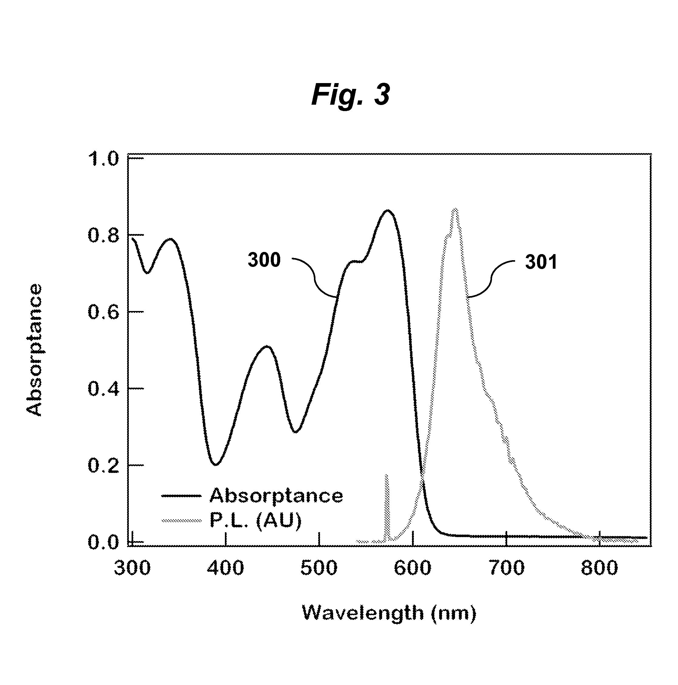
[0049]The 3 mm thick luminescent sheet contains polymethylmethacrylate (PMMA) with a fluorescent dye, Lumogen 305, is diluted into the sheet at a concentration of 0.006% by weight percent of Lumogen 305 in PMMA. A silicon PV cell is attached directly to the acrylic using an optical clear glue that is thermally stable above 85 C and allows for differential thermal expansion. A thin plastic sheet is laminated to the back of the substrate for protection. At 16% area of PV per area of luminescent sheet, the power efficiency is approximately 4%. The sheet absorbs less than 60% of the photons between 410 and 490 nm and less than 10% of the photons between 620 and 680 nm, and approximately 70% of the photons between 500 and 600 nm.

example 2

[0050]The 0.5 mm thick luminescent sheet contains polymethylmethacrylate (PMMA) with a fluorescent dye, Lumogen 305, diluted into the sheet at a concentration of 0.03% by weight percent of LR305 in PMMA. This film and the silicon PV cells are laminated to a glass or acrylic sheet that is 3 mm thick using EVA. A thin glass sheet is laminated with EVA to the back of the substrate for protection purposes. At 16% coverage, the power efficiency is approximately 4.5% and the sheet absorbs less than 60% of the photons between 410 and 490 nm and less than 10% of the photons between 600 and 690 nm, and approximately 70% of the photons between 500 and 600 nm.

example 3

[0051]The 0.2 mm thick luminescent sheet contains polymethylmethacrylate (PMMA) with a fluorescent dye, Lumogen 305, diluted into the sheet at a concentration of 0.1% by weight percent of Lumogen 305 in PMMA. The silicon PV cell is attached to a supporting frame, and the luminescent sheet is coupled to the silicon PV using an optical glue. At 10% coverage, the power efficiency is approximately 3% and the sheet absorbs less than 50% of the photons between 410 and 490 nm and less than 10% of the photons between 600 and 690 nm, and approximately 60% of the photons between 500 and 600 nm.


PUM


Abstract

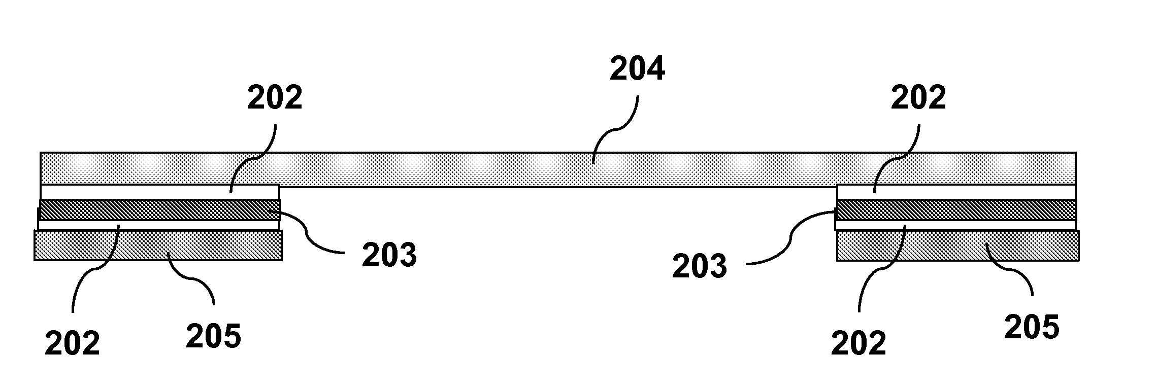
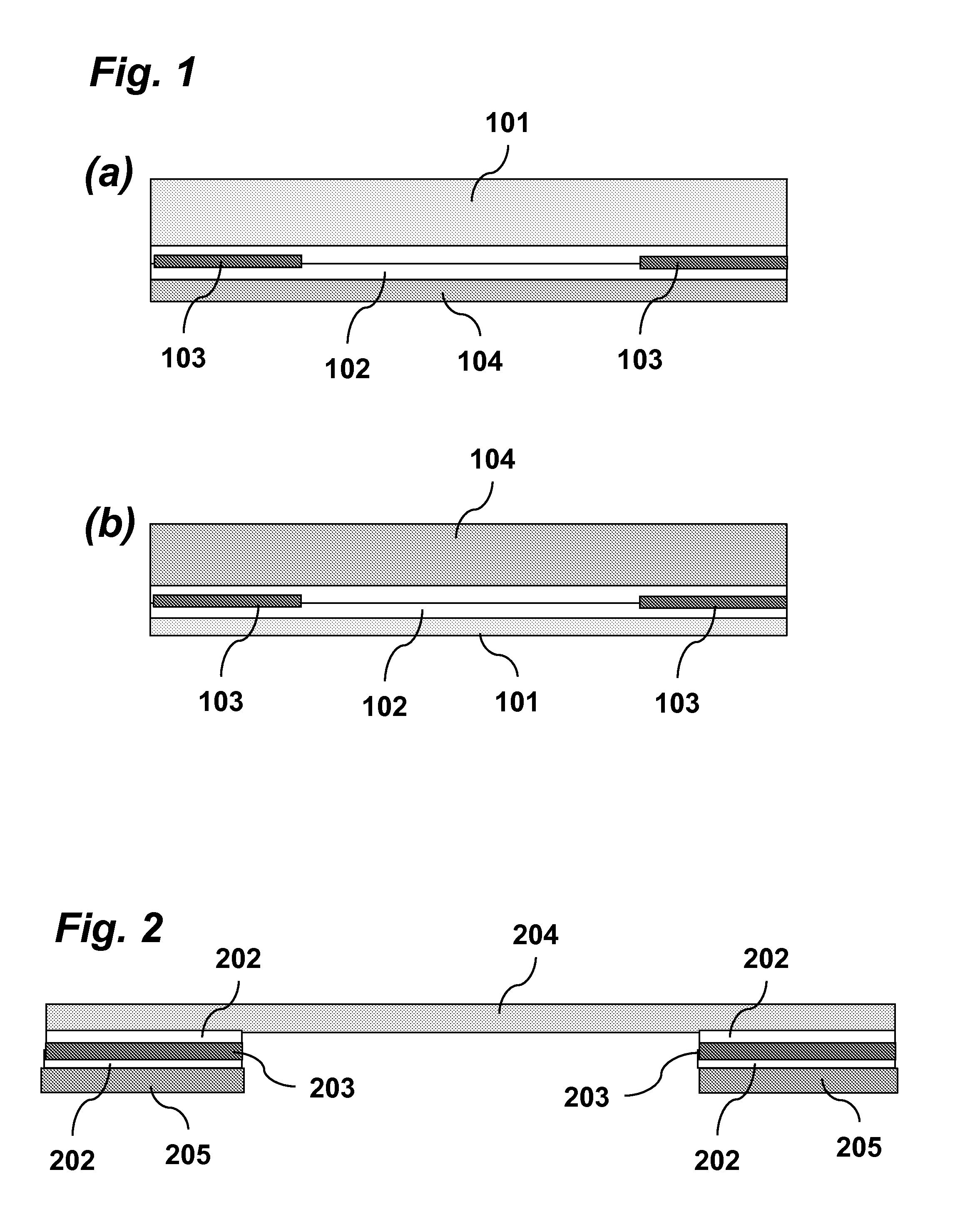
A window for a greenhouse is provided that is comprised of a sheet of luminescent material [104] and light-energy converter [103]. The sheet comprises one or more luminescent materials [104] that absorb the peak wavelengths of the sun, emitting the absorbed photons to wavelengths primarily between 600 and 690 nm where they are converted to electrical power and / or enhance plant production. The luminescent material [104] is also transparent to a fraction of the wavelengths in the blue and red-portion of the solar spectrum which are required for plant growth and flowering. An additional polymer layer may be added as a luminescent layer, diffuser and / or IR reflector to further enhance plant growth and electricity generation.

Description

FIELD OF THE INVENTION[0001]This invention relates generally to luminescent solar collectors and building integrated photovoltaic windows.BACKGROUND OF THE INVENTION[0002]Luminescent Solar Collectors (LSCs) are beneficial for capturing solar energy for conversion to electrical power. An LSC has a sheet containing a fluorescent material that absorbs solar radiation from the sun after which it emits photons to longer wavelengths through the process of photoluminescence or fluorescence. The light, or photons, that are emitted through this process are waveguided (via total internal reflection) down a sheet that is coupled to a photovoltaic cell or solar cell that converts the light to electrical power. Current approaches of LSCs focus on maximizing the power conversion efficiency of the LSC with little regard to the application of this technology as building integrated PV windows for greenhouses and related structures where plant growth is important.[0003]Adjusting the spectrum, or colo...

Claims


Application Information

Patent Timeline
IPC IPC(8): H01L31/055
CPCH01L31/055A01G7/045A01G9/243A01G9/249Y02E10/52Y02A40/25Y02P60/12Y02P60/14
Inventor CARTER, SUE A.ALERS, GLENN B.LOIK, MICHAEL E.
Owner RGT UNIV OF CALIFORNIA
Learn More