Controller for a brushless motor

Active Publication Date: 2014-12-18
DYSON TECH LTD
View PDF2 Cites 16 Cited by
  • Summary
  • Abstract
  • Description
  • Claims
  • Application Information

AI Technical Summary

Benefits of technology

[0011]The controller may comprise a first PWM module configured in half-bridge mode, and a second PWM module configured in half-bridge mode. The first PWM module then modulates the control signals during one half of an electrical cycle of the motor, and the second PWM module modulates the control signals for the other half of the electrical cycle. Two PWM modules configured in half-bridge mode have the advantage that the control signals may be used to close both low-side switches of an inverter during freewheeling. As a result, the efficiency of the motor may be improved. Two PWM modules have the further advantage that the modules may operate without ever needing to generate a software interrupt. In particular, the first PWM module may be updated during the cycle of the second PWM module, and the second PWM module may be updated during the cycle of the first PWM module. As a result, one PWM module may be updated without interrupting the operation of the other PWM module. Moreover, each PWM module may be updated at time that is convenient for the processor of the controller.
[0012]The controller may receive a rotor-position signal having edges, and the controller may comprise a processor that updates the first PWM module in response to a rising edge in the rotor-position signal, and updates the second PWM module in response to a falling edge in the rotor-position signal. The two

Problems solved by technology

Consequently, should two interrupts occur at the same time, the execution of one of the ISRs will be delayed.
This delay may then adversely

Method used


Image

  • Controller for a brushless motor
  • Controller for a brushless motor
  • Controller for a brushless motor

Examples


Embodiment Construction

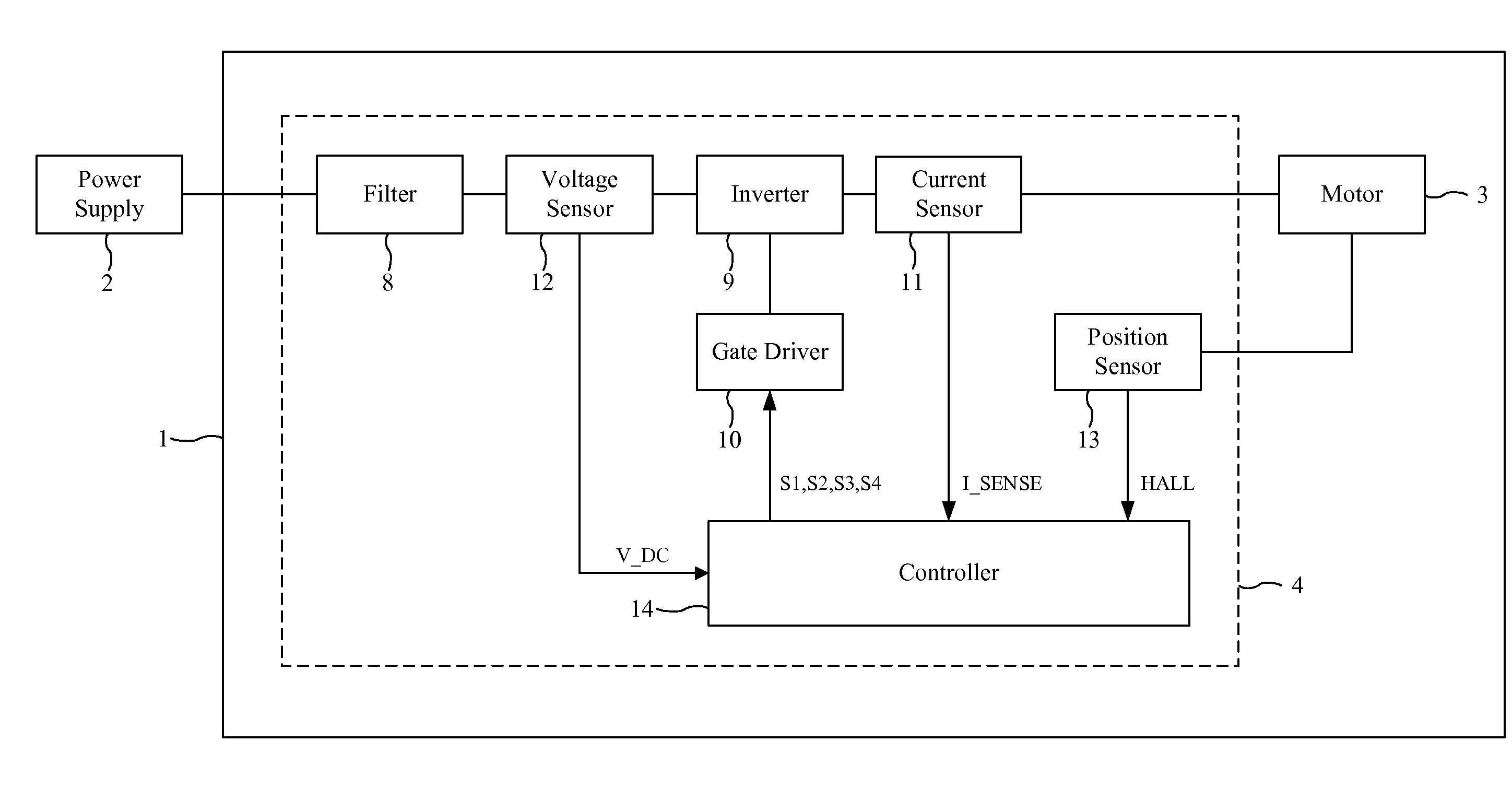
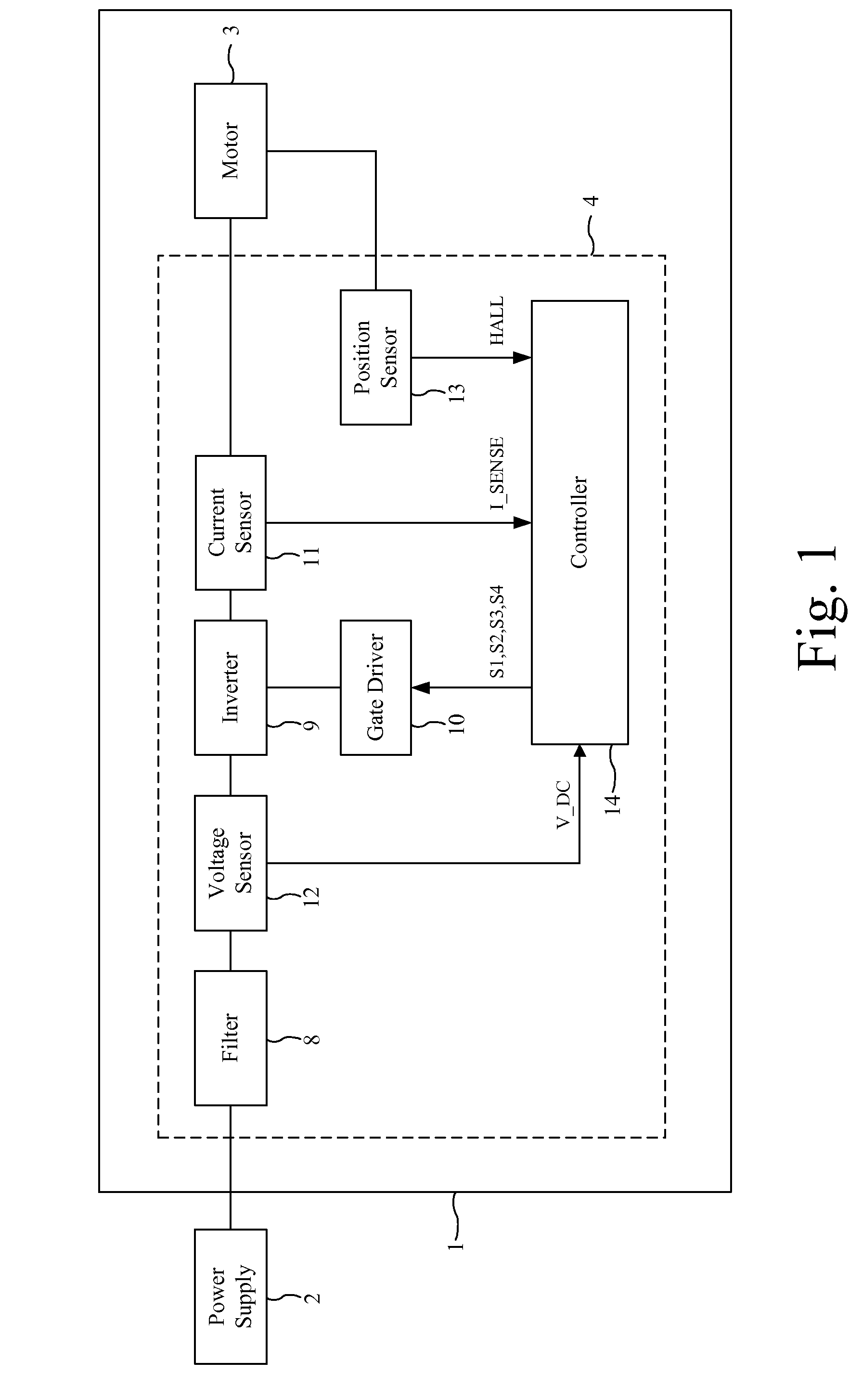
[0030]The motor assembly 1 of FIGS. 1 and 2 is powered by a DC power supply 2 and comprises a brushless motor 3 and a control circuit 4.

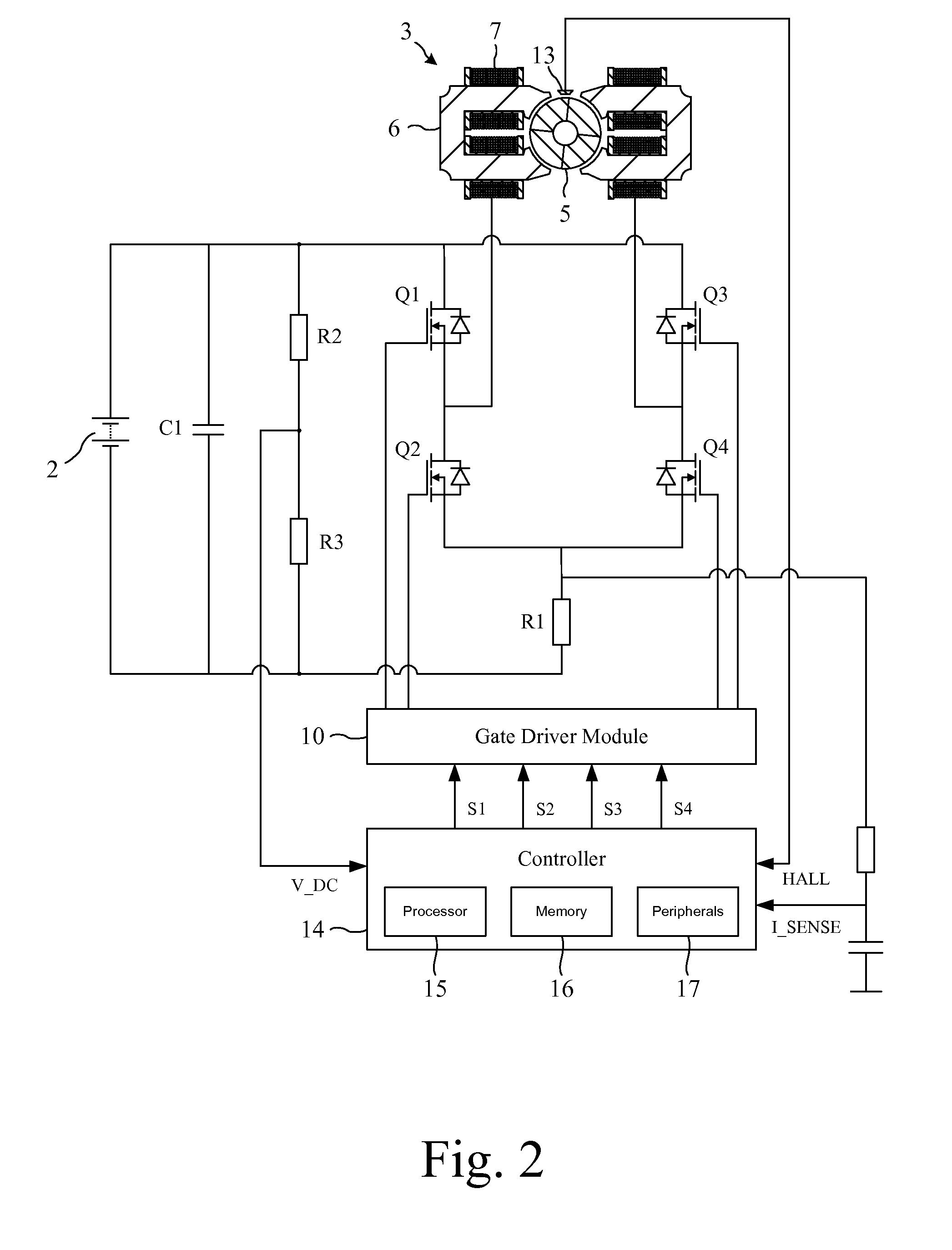
[0031]The motor 3 comprises a four-pole permanent-magnet rotor 5 that rotates relative to a four-pole stator 6. Conductive wires wound about the stator 6 are coupled together to form a single phase winding 7.

[0032]The control circuit 4 comprises a filter 8, an inverter 9, a gate driver module 10, a current sensor 11, a voltage sensor 12, a position sensor 13, and a controller 14.

[0033]The filter 8 comprises a link capacitor C1 that smoothes the relatively high-frequency ripple that arises from switching of the inverter 9.

[0034]The inverter 9 comprises a full bridge of four power switches Q1-Q4 that couple the phase winding 7 to the voltage rails. Each of the switches Q1-Q4 includes a freewheel diode.

[0035]The gate driver module 10 drives the opening and closing of the switches Q1-Q4 in response to control signals received from the controller 14.

[003...


PUM


Abstract

A controller for a brushless motor that includes a PWM module configured in half-bridge or full-bridge mode. The PWM module outputs control signals for controlling the excitation of a winding of the motor, and one of the duty cycle and the period of the PWM module defines a time at which the winding is commutated.

Description

REFERENCE TO RELATED APPLICATION[0001]This application claims priority of United Kingdom Application No. 1310567.1, filed Jun. 13, 2013, the entire contents of which are incorporated herein by reference.FIELD OF THE INVENTION[0002]The present invention relates to a controller for a brushless motor.BACKGROUND OF THE INVENTION[0003]The controller of a brushless motor typically comprises a processor for executing different software routines in response to different events. A common method of event handling is through the use of interrupts. In response to an interrupt, the processor interrupts execution of the main code and services the interrupt by executing an interrupt service routine (ISR). When executing an ISR, the processor is unable to service any other interrupts. Consequently, should two interrupts occur at the same time, the execution of one of the ISRs will be delayed. This delay may then adversely affect the performance of the motor. For example, the controller may employ a...

Claims


Application Information

Patent Timeline
IPC IPC(8): H02P6/00H02P6/18H02P6/14
CPCH02P6/002H02P6/182H02P6/142H02P7/29H02P6/15H02P6/28H02P6/157H02P6/085H02P6/14
Inventor ZHOU, YONGJIZHENG, LIBODAI, HANPING
Owner DYSON TECH LTD
Why Eureka
Try Eureka