
Spray dryer exhaust treatment and anaerobic digester

a technology of anaerobic digestion and spray dryer, which is applied in the direction of biochemistry equipment and processes, lighting and heating equipment, biochemistry apparatus, etc., can solve the problems of high cost of exhaust gas treatment, high cost of process, and high cost of process. large amount of natural gas

Inactive Publication Date: 2015-01-01
ANAERGIA
View PDF9 Cites 2 Cited by
  • Summary
  • Abstract
  • Description
  • Claims
  • Application Information

AI Technical Summary

Benefits of technology

The patent describes a system for treating the exhaust gas from a spray dryer used to dry digestate from an anaerobic digester. The system recovers waste heat, removes contaminants from the exhaust gas, or both. The system can reduce odors from the exhaust gas by removing odorous compounds as condensate, by combustion, or both. The system can also reduce energy consumption by recirculating at least some of the spray dryer exhaust, recovering heat from the exhaust gas, or using waste heat from a biogas burner. The spray dried product can be used as a fertilizer or soil enhancing product.

Problems solved by technology

If a spray drier is used to dry digestate from an anaerobic digester, and possibly other mixtures, the exhausted air will be contaminated with volatile organics and have a foul odor.
However, when drying digestate the high volume of air and the corresponding low concentration of volatile organics would render the calorific value of the exhaust gas too low for effective treatment using this process.
However, this process would consume a large amount of natural gas with the heat energy required to treat the exhaust exceeding the heat energy required in the spray dryer itself.
Although the quality of a spray dried product is typically very high, the energy consumption of a spray dryer using a gas fired thermal oxidizer to treat the exhaust gas would discourage the use of a spray dryer with digestate.

Method used


Image

  • Spray dryer exhaust treatment and anaerobic digester
  • Spray dryer exhaust treatment and anaerobic digester

Examples


Embodiment Construction

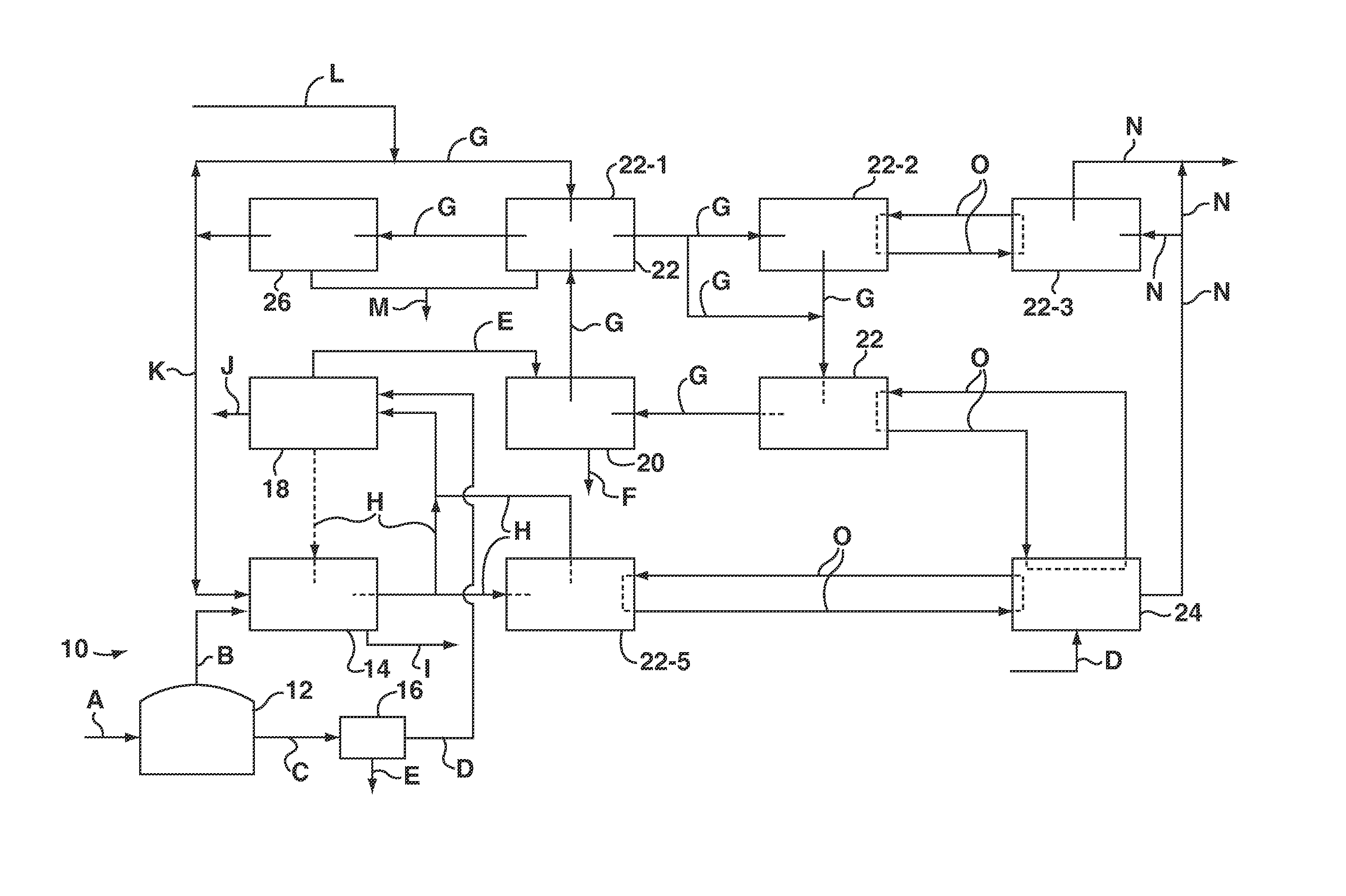
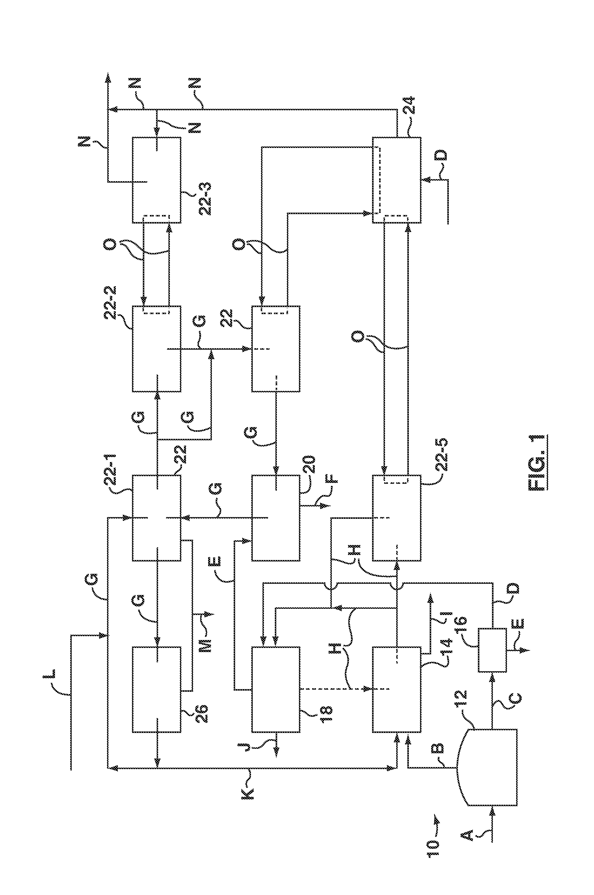
[0011]FIG. 1 shows an anaerobic digester 10. The anaerobic digester 10 has, among other things, a reactor 12, a biogas burner 14, an optional solid-liquid separation unit 16, an optional evaporator 18 and a spray dryer 20. The reactor 12 may have one or more covered tanks with mixers. Though not shown, the reactor 12 may also have a feed storage and conveying system, internal mixers, a heater, a service box, a digestate recirculation loop, or other known equipment used with anaerobic digesters. The biogas burner 14 may be a combined heat and power (CHP) unit. A CHP unit may be a reciprocating or turbine engine capable of burning methane and turning a generator to produce electricity, or a boiler producing steam that is used to turn a generator. The solid-liquid separation unit 16 may be, for example, a screw press or belt press. A screening surface in the solid-liquid separation unit may have an opening size of at least 500 microns. The evaporator 18 may be, for example, a self-clea...


PUM


Abstract

A spray dryer exhaust gas treatment system and process recovers waste heat, removes odors from the exhaust gas, or both. The spray dryer may be used to dry digestate from an anaerobic digester. Spray dryer exhaust is at least partially recirculated to the spray dryer, or condensable vapors are removed from the spray dryer exhaust, or both. Optionally, a bleed from a recirculating exhaust stream may pass through a combustion chamber. Preferably, waste heat is added to the recirculating exhaust stream or used to evaporate water upstream of the spray dryer. In a case where the spray dryer is used to treat digestate, a biogas burner may provide the combustion chamber and a source of waste heat. The system and method reduce odors from spray dryer exhaust by condensing odorous compounds, by combustion, or both while using waste heat and spray dryer exhaust gas recirculation to reduce energy consumption.

Description

RELATED APPLICATIONS[0001]This application claims the benefit of U.S. Provisional Application No. 61 / 840,078 filed Jun. 27, 2013, which is incorporated herein by reference.FIELD[0002]This specification relates to spray dryers and to anaerobic digestion.BACKGROUND[0003]Spray drying is used in some industrial drying applications. The spray dryer produces particles or agglomerates that can often meet rigorous quality specifications relating to particle size distribution, bulk density or particle morphology. Spray dryers use direct contact between air, or another gas, and a solid-liquid mixture being dried. Thermal mass transfer heating takes place over a very short contact time. The mixture is atomized and the droplets are combined with a hot air stream. The hot air stream removes moisture from the atomized particles and then the hot air and dried particles are separated. For example, the hot air stream may pass through a cyclone in order to remove relatively large particles. Following...

Claims


Application Information

Patent Timeline
IPC IPC(8): F26B23/00F26B3/02
CPCF26B3/02F26B23/002F26B25/005F26B3/12Y02W10/23C12M47/14Y02E50/30Y02P70/10
Inventor KUMAR, ASHWANIPHAGOO, DEONARINEJOSSE, JUAN CARLOS
Owner ANAERGIA
Learn More