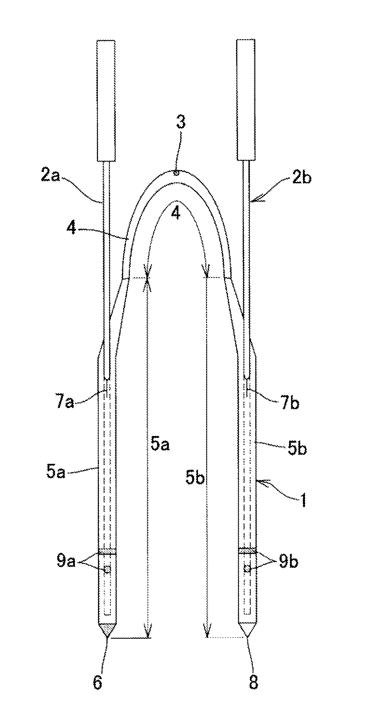
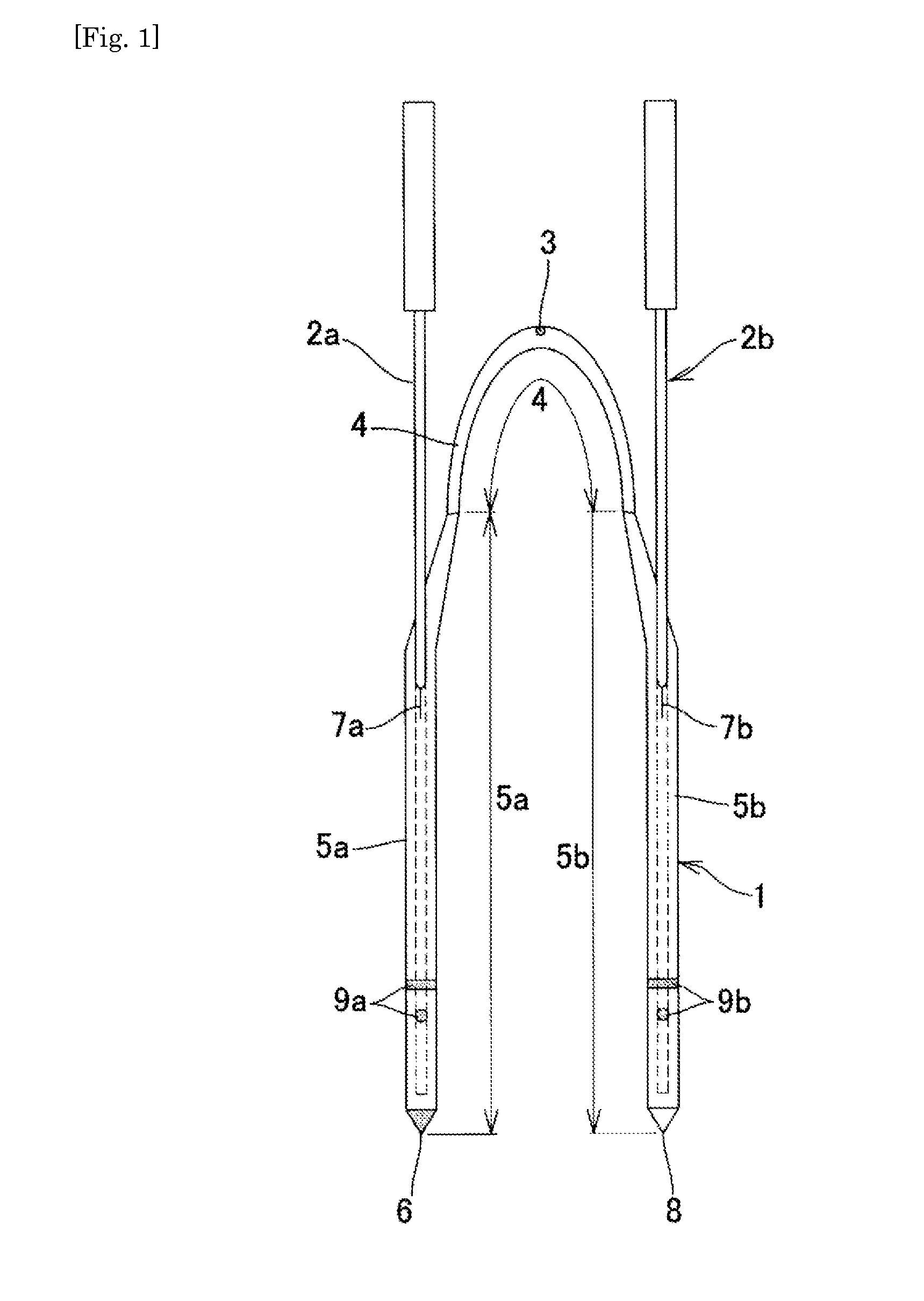
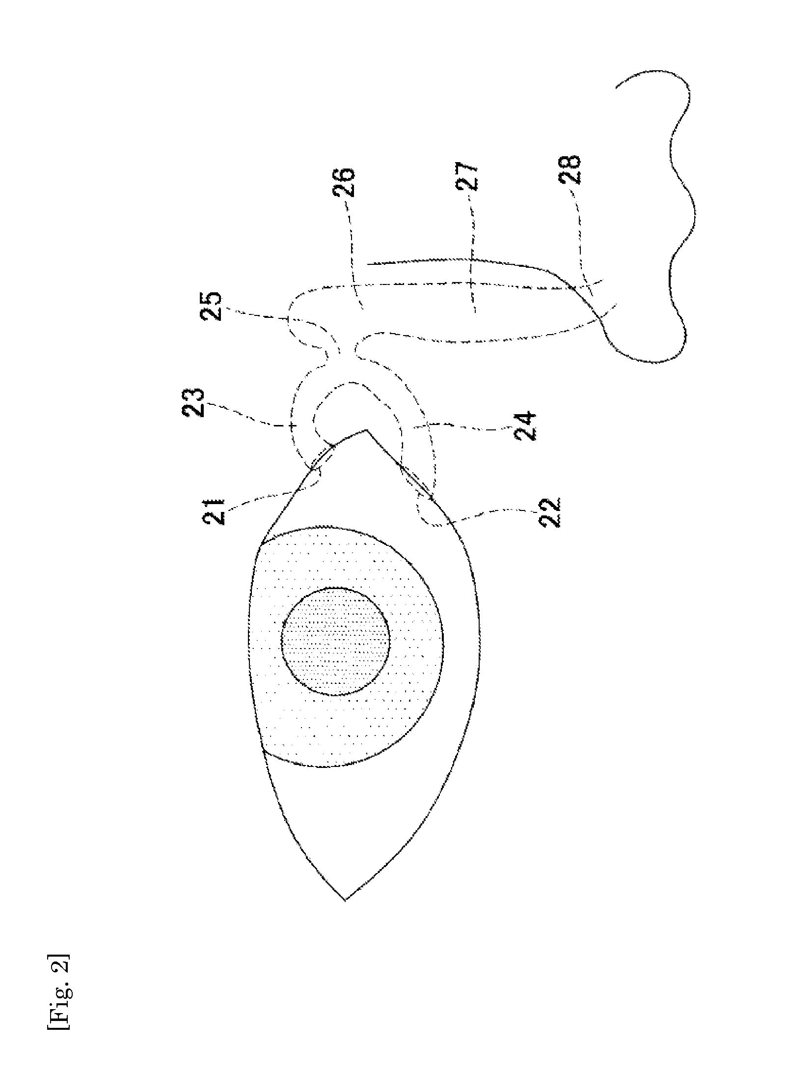
Medical tube

a technology for medical devices and tubes, applied in the field of medical devices, can solve the problems of difficulty in correctly inserting the tube into the curved or obstructed lacrimal duct, the difference in treatment, and the cost of devices, so as to reduce the drop of the lubricant layer, improve the durability, and facilitate the insertion into the living body

Active Publication Date: 2015-01-15
KANEKA CORP
View PDF1 Cites 5 Cited by
  • Summary
  • Abstract
  • Description
  • Claims
  • Application Information

AI Technical Summary

Benefits of technology

[0040]According to the present invention, the lubricant layer composed of a specific composition provides sufficient lubricity to the surface of the insertion member in wet conditions, and thus the medical tube can be easily inserted into a living body. In addition, the lubricant layer is further improved in durability than conventional ones, and makes it possible to suppress dropping of the lubricant layer from the surface of the insertion member.
[0041]In addition, if the medical tube is a lacrimal duct tube, for example, the surface of the lacrimal duct tube is sufficiently lubricant in wet conditions, which makes it possible to reduce friction between a lacrimal duct wall and the tube. In addition, if any force is applied to the tube so as to form a false passage, resistance to the operator's hand becomes large, and thus the formation of a false passage can be recognized from a difference in resistance to the operator's hand. This makes it possible to insert the lacrimal duct tube in an easy and correct manner into a curved or obstructed lacrimal duct and place the same there under no overload and without breaking through the lacrimal duct tube or formation of a false passage. Further, the intermediate layer and the lubricant layer composed of specific compositions are sequentially laminated on the surface of the placement member, and thus the tube is improved in durability and thus is preferably used as a lacrimal duct tube that is supposed to be placed for a long period of time (for example, about two weeks to two months).
[0042]Moreover, if the medical tube is a catheter that is inserted into a bent blood vessel or the like, such as an occlusion catheter, for example, the surface of the occlusion catheter is sufficiently lubricant in wet conditions, and thus resistance of contact with a blood vessel wall or the like decreases to improve insertability. In addition, the tube is improved in durability, which makes it possible to suppress dropping of the lubricant layer even if the tube is inserted by a certain distance during passage through a bent portion of the blood vessel.

Problems solved by technology

The bougies in the lacrimal duct tube are blindly operated, and it is thus difficult to correctly insert the tube into a curved or obstructed lacrimal duct.
If an operator feels large resistance at insertion of the tube, he / she cannot easily determine whether the resistance results from friction between a wall of an obstructed site in the lacrimal duct and the lacrimal duct tube, or results from the bougie's breaking through the lacrimal duct tube, or results from formation of a temporal path (making a hole in a portion other than the lacrimal duct), or the like, and he / she actually forms a false passage in many cases.
In addition, as treatments using an endoscope have been performed on increasing occasions, it has been found that there has been a difference in treatment results between the case of correctly placing the lacrimal duct tube in a lacrimal duct and the case of placing the lacrimal duct tube in a temporal path.
As described above, although it has been recognized that operations using a lacrimal endoscope are very effective in insertion of the lacrimal duct tube into a lacrimal duct, lacrimal endoscopes are installed in a limited number of hospitals under the present circumstances, for a reason that the devices are expensive and the like.
However, using the coating described in Patent Document 2 or Non-patent Document 1 has not necessarily realized sufficient insertability and the like in practical use under the present circumstances.
However, it is not easy to guide the long tube by in-vitro operations to a desired site within the bent blood vessel.
However, there remains the possibility that the coating partially comes off of the surface when the catheter is placed in a living body for a long period of time or when the catheter is inserted by a certain distance during passage through a bent portion of a blood vessel or the like.

Method used


Image

  • Medical tube
  • Medical tube
  • Medical tube

Examples


example 1

Production of Coating Liquids

(1) Preparation of Liquid A

[0145]The following substance was put into a 10 L reactor.

4,4′-diphenylmethane diisocyanate6.0[kg]

[0146]The substance was heated up to 70° C. while being stirred in a nitrogen stream. Then, the following substance was continuously dripped into the former substance over two hours while the former substance was further stirred.

Ricinus oil3.2[kg]

[0147]The substance was further continuously stirred at 70° C. in a nitrogen stream for two hours, thereby obtaining a polyurethane pre-polymer.

(2) Preparation of Liquid B

[0148]The liquid A was blended 4.8 g with 1.2 g of ricinus oil and 34 g of THF, and well stirred to obtain liquid B.

(3) Preparation of Liquid C

[0149]The liquid B was blended 5 g with 25 g of a solution with 10 weight % of THF in polyethylene glycol 4000 (PEG4000), and stirred at 40° C. for three hours, thereby obtaining liquid C. The concentration of components other than THF (coating composition) in the obtained liquid C...

example 2

Production of Coating Liquids

[0159]In the same manners as in (1) to (5) of example 1, liquid A, liquid B, liquid C (1), liquid C (1 / 4), liquid C (1 / 8), liquid D (1), liquid D (1 / 4), and liquid E (1 / 4) were prepared.

[0160]In addition, as in the same manner as in (3) of example 1, a portion of the liquid C (1) was blended with THF for 16-fold dilution to prepare liquid C (1 / 16) in which the concentration of the coating composition was 0.57 weight %, and the same operation was performed for 32-fold dilution to prepare liquid C (1 / 32) in which the concentration of the coating composition was 0.29 weight %.

[0161]As indicated in Table 4, the liquid C (1 / 32), liquid C (1 / 16), and liquid C (1 / 8) were used as intermediate layer coating liquids, and the liquid E (1 / 4) was used as a lubricant layer coating liquid to obtain a tube in which an intermediate layer and a lubricant layer were sequentially laminated on the surface of the tube, in the same manner as in example 1. The obtained tubes we...

example 3

Production of Coating Liquids

[0162]In the same manners as in (1) to (4) of example 1, liquid A, liquid B, liquid C (1), liquid C (1 / 2), liquid D (1), and liquid D (1 / 2) were prepared. The same amounts of the liquid C (1 / 2) and D (1 / 2) with the same dilution ratio of the coating composition were mixed together and stirred at 40° C. for one hour, thereby obtaining liquid H (1 / 2). Table 1 shows the composition ratio of the liquid H.

[0163]A tube with an outer diameter of 1.0 mm and a length of 200 mm produced by Pebax was used.

[0164]The tube was dipped in the liquid C (1 / 2) as an intermediate layer coating liquid, and was pulled out in parallel to the length of the tube at a constant speed of 10 mm / sec, thereby to coat the liquid C (1 / 2) to the surface of the tube. After that, the tube was dried for one hour at room temperature to form an intermediate layer on the surface of the tube.

[0165]The tube was dipped in the liquid H (1 / 2) as a lubricant layer coating liquid, and was pulled out ...


PUM

PropertyMeasurementUnit
weight %aaaaaaaaaa
weight %aaaaaaaaaa
weight %aaaaaaaaaa

Abstract

A medical tube in which an intermediate layer composed of a composition containing (a), (b), and (c1) listed below and a lubricant layer composed of a composition containing (a), (b), and (c2) listed below are sequentially laminated on a surface of an insertion member to be inserted into a living body: (a) 1 to 35 weight % of at least one of aromatic diisocyanate, aliphatic diisocyanate, and alicyclic diisocyanate; (b) 1 to 35 weight % of trifunctional or higher functionality polyol; (c1) 30 to 98 weight % of polyalkylene glycol and/or monomethoxypolyalkylene glycol; and (c2) 30 to 98 weight % of polyalkylene glycol (including polyalkylene glycol larger in weight-average molecular weight than polyalkylene glycol in (c1)) and/or monomethoxypolyalkylene glycol (including monomethoxypolyalkylene glycol larger in weight-average molecular weight than monomethoxypolyalkylene glycol in (c1)),
(where each of the glycols in (c1) and (c2) is diol).

Description

TECHNICAL FIELD[0001]The present invention relates to a medical tube that is inserted into a living body, for example, a lacrimal duct, a blood vessel, and the like.BACKGROUND ART[0002]Conventionally, it has been widely employed a medical tube to be inserted into a portion of a living body such as a lumen, which has a layer with lubricity (lubricant layer) on the surface of an insertion member to be inserted into a living body. It is considered that forming such a layer reduces resistance of contact between the insertion member inserted into the living body and the living body, which makes it possible to improve insertability of the medical tube and alleviate distress in a patient and damage to the body of the patient.[0003]In what follows, taking as examples treatments for lacrimal duct obstruction, intravascular disease, and the like in which a treatment tube with the lubricant layer may be used, background arts of lacrimal duct tube and occlusion catheter for use in these treatme...

Claims


Application Information

Patent Timeline
Patent Type & Authority Applications(United States)
IPC IPC(8): A61M25/00B05D1/28B05D1/18B05D1/02A61F2/82A61F2/00
CPCA61M2025/0046B05D1/02B05D1/28A61F2210/0076B05D1/18A61M2207/00A61F2/82A61F2/0077A61M25/0045A61F9/00772A61L29/085A61L29/14A61L2400/10A61L2420/08A61M25/0009C08L75/04
Inventor MATSUMOTO, MARIKOMATSUMURA, YOICHIMIYAUCHI, HIDEKAZU
Owner KANEKA CORP
Why Eureka
Try Eureka