Lithium microbattery fabrication method

Active Publication Date: 2015-01-29
COMMISSARIAT A LENERGIE ATOMIQUE ET AUX ENERGIES ALTERNATIVES
View PDF3 Cites 3 Cited by
  • Summary
  • Abstract
  • Description
  • Claims
  • Application Information

AI Technical Summary

Benefits of technology

The invention provides a simple and inexpensive method for making lithium microbatteries that can be used in the microelectronics field. This allows for the easy integration of batteries into smaller electronic devices.

Problems solved by technology

However, a lithium microbattery is very sensitive to air and to moisture.
The lithium-base layers are in fact very reactive and very chemically unstable.
The presence of lithium, and in certain cases of sulphur, in thin layers forming a microbattery gives these layers a highly hygroscopic nature and a chemical instability in air.
This type of thin layers, in particular the layers of solid electrolyte, are in fact difficult to pattern.
This masking technique generates particle contamination and shadow masking can also scratch the layer on which it is placed, thereby being liable to damage the microbattery considerably.
Furthermore, when the size of the microbattery is small, shadow masking can generate edge or shadow effects which prove detrimental for satisfactory operation of the microbattery.
This method can further require the use of different devices, which increases the risk of exposure of the solid electrolyte layer to air and moisture.
Implementation of this fabrication method is therefore slow and complex.

Method used


Image

  • Lithium microbattery fabrication method
  • Lithium microbattery fabrication method
  • Lithium microbattery fabrication method

Examples


Embodiment Construction

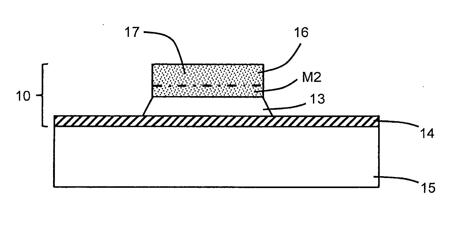
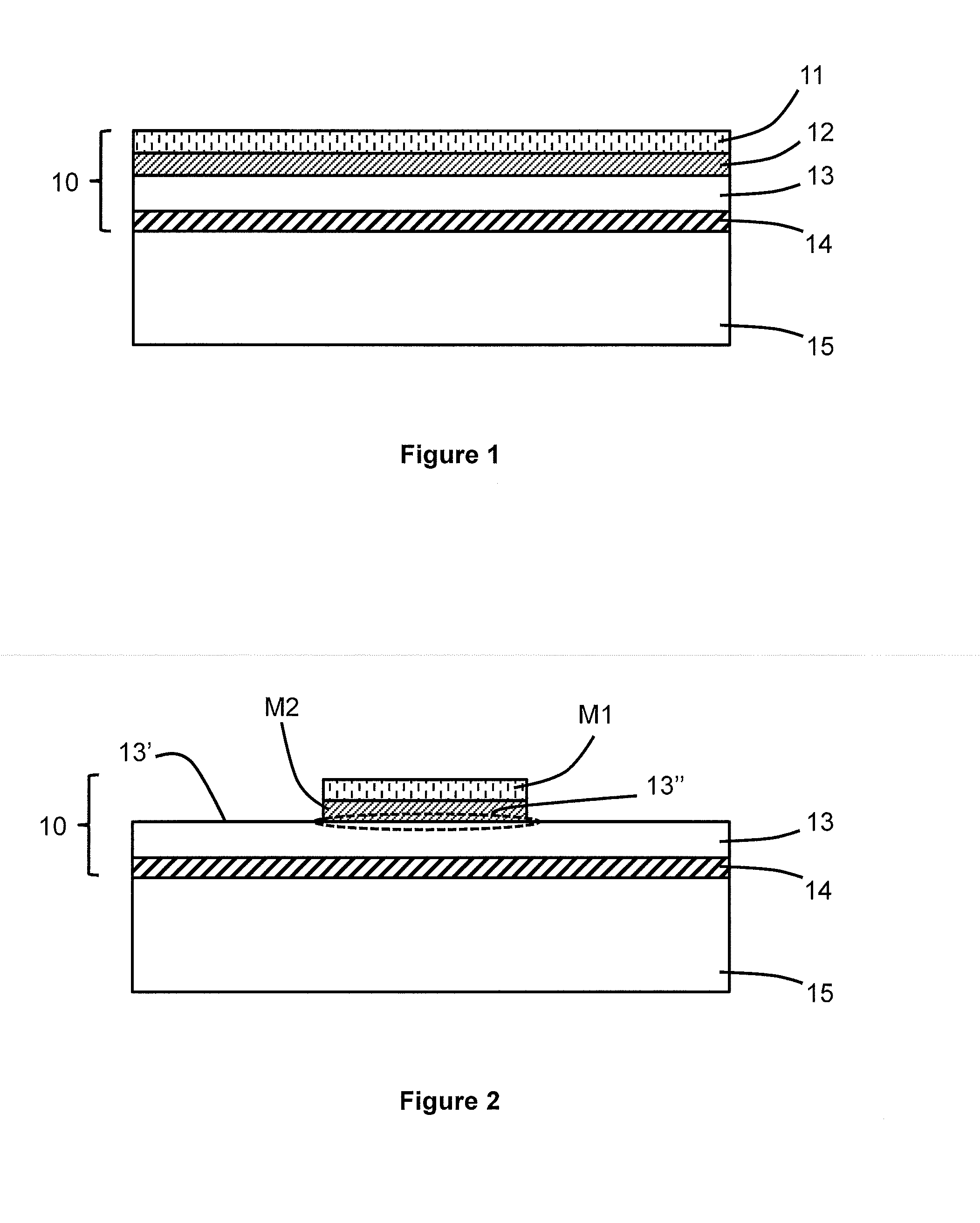
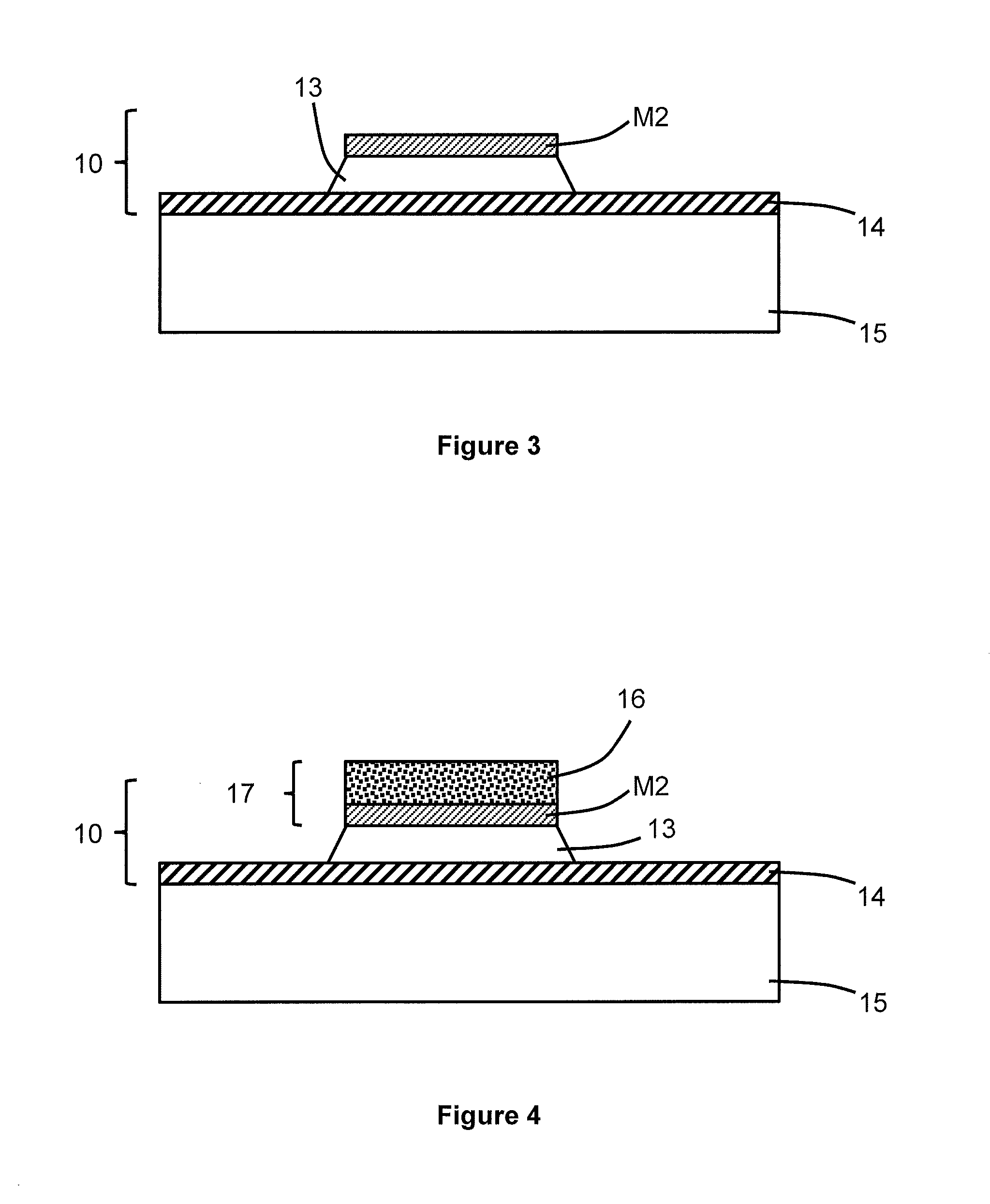
[0039]According to a first embodiment illustrated in FIGS. 1 to 5, the method comprises provision of a stack 10 successively comprising a first layer 11 made from first material, a second layer 12 made from second material, a solid electrolyte layer 13 and a first electrode 14. In particular, thin layers 12 to 14 are designed to form a lithium microbattery.

[0040]Thin layers 11 to 14 can be deposited successively on a substrate 15 by conventional microelectronics industry techniques, for example by Physical Vapor Deposition (PVD), vacuum evaporation deposition, or Chemical Vapor Deposition (CVD). The thickness of thin layers 11 to 14 can vary between a few nanometres and a few tens of micrometres.

[0041]Substrate 15 is generally a silicon wafer able to comprise an integrated circuit, the substrate can also be made from glass or ceramic. Substrate 15 can be covered by a passivation layer, typically formed by silicon oxide, or by a bilayer formed by a layer of oxide and a layer of silic...


PUM

PropertyMeasurementUnit
Fractionaaaaaaaaaa
Concentrationaaaaaaaaaa
Areaaaaaaaaaaa

Abstract

The method for fabricating a lithium microbattery is performed from a stack of layers successively including: a first layer made from a first material, a second layer made from a second material, a solid electrolyte layer and a first electrode. The method further includes etching to form a first pattern made from the first material and a second pattern made from the second material, the second pattern defining a covered area and an uncovered area of the electrolyte layer. The uncovered area is then etched using the second pattern as etching mask. After etching of the first pattern, a lithium-based layer is formed on the second pattern, the lithium-based layer and the second pattern forming a second lithium-based electrode.

Description

BACKGROUND OF THE INVENTION[0001]The invention relates to patterning of a layer of solid electrolyte, in particular to produce a lithium microbattery.STATE OF THE ART[0002]A lithium microbattery is an electrochemical accumulator implementing Li+ ions and comprising an active stack of thin layers. The active stack is formed by two electrodes, one positive and the other negative, separated by a solid electrolyte.[0003]The solid electrolyte is an electric insulator having a high ionic conductivity. The solid electrolyte generally has a base formed by a lithiated component. Furthermore, the positive electrode is a lithium insertion material, for example a lithiated metal oxide.[0004]Lithium microbatteries called “lithium-metal” microbatteries comprise a negative electrode made from metallic lithium. Furthermore, lithium microbatteries called “lithium-ion” microbatteries comprise a negative electrode formed by a lithium insertion or intercalation material.[0005]Lithium microbatteries are...

Claims


Application Information

Patent Timeline
IPC IPC(8): H01M10/04H01M10/38H01M4/38H01M4/04H01M6/04H01M6/40
CPCH01M10/04H01M6/045H01M6/40H01M2300/0002H01M4/0407H01M4/0492H01M10/38H01M4/382H01M4/1395H01M6/186H01M6/187H01M10/052H01M10/0562H01M10/0585Y02E60/10Y02P70/50B81C1/00396B81C1/00412C09K13/04C23F1/02C23F4/00G03F7/094H01M4/0421H01M4/0426H01M4/045
Inventor OUKASSI, SAMIBAZIN, ARNAUD
Owner COMMISSARIAT A LENERGIE ATOMIQUE ET AUX ENERGIES ALTERNATIVES
Why Eureka
Try Eureka