
Conveyor belt

a conveyor belt and belt technology, applied in the field of conveyor belts, can solve the problems of relatively long conveyor belt so employed, and high cost component of industrial material handling operation, so as to improve the wear resistance of conveyor belts, improve the resistance to surface damage, and improve the effect of adhesion

Inactive Publication Date: 2015-02-05
CONTITECH USA INC
View PDF7 Cites 11 Cited by
  • Summary
  • Abstract
  • Description
  • Claims
  • Application Information

AI Technical Summary

Benefits of technology

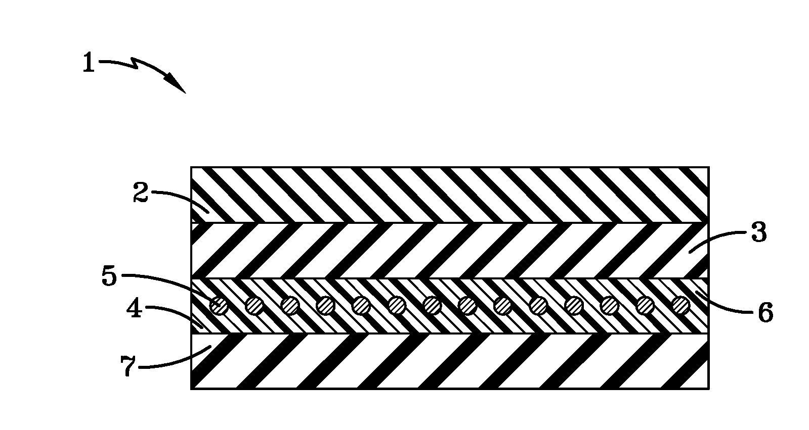
This patent is about a new way to make conveyor belts that are more durable and resistant to damage. It involves adding a layer of polyurethane to the belt's surface as a carry cover, which can be attached using standard rubber processing equipment. The use of a tie gum layer made of polyvinylchloride and nitrile rubber helps to bond the polyurethane layer to the reinforcement layer of the belt. This new method results in conveyor belts that can be used for heavy duty applications, like mining, which offer a longer service life, reduce down-time, and improve overall productivity. This method doesn't negatively impact worker health or safety, and it's environmentally friendly.

Problems solved by technology

The conveyor belts so employed may be relatively long, for example, on the order of miles, and represent a high cost component of an industrial material handling operation.
Heavy duty conveyor belts used in mining operations can extend over distances of many miles and represent a high cost component of an industrial material handling operation.
All conveyor belts are, of course, susceptible to normal wear and tear as well as damage from the material being transported and / or harsh environmental conditions.
Unfortunately, conveyor belts which are used in mining operations are particularly susceptible to damage from the material transported thereon and a rip, slit, cut or tear may develop on the surface of the belt which comes in contact with the material being transported (the carry cover surface of the belt).
For instance, sharp edges of the material being transported, such as iron ore and copper ore which are particularly abrasive, can gouge the surface of the belt and that can result in a rip developing and propagating deeper into the body of the belt.
Such damage can ultimately result in belt failure.
In the event the conveyor belt suffers catastrophic damage or otherwise becomes inoperable, the costs of repairing the conveyor belt, cleaning up the spilt material, and related downtime can be substantial.
However, these improvements were only incremental by virtue of being based upon blends of standard general purpose elastomers, such as styrene-butadiene rubber (SBR), natural rubber, and polybutadiene rubber.

Method used


Image

  • Conveyor belt
  • Conveyor belt
  • Conveyor belt

Examples


examples 1-3

[0032]In this experiment a series of polyurethane rubber formulations for utilization in a conveyor belt carry cover layer were prepared. These rubber formulations had the compositions and physical properties depicted in Table 1.

TABLE 1Example123Millathane ® E34100.0parts100.0parts100.0partspolyether millableurethane rubber*Zinc Stearate0.5parts0.5parts0.5partsN330 Carbon Black30.0parts25.0parts—N220 Carbon Black——25.0partsDibutoxyethoxyethyl5.0parts5.0parts5.0partsAdipateAliphatic Fatty Acid1.0parts1.0parts1.0partsEsterSulfur1.5parts1.5parts1.5partsMBTS (Benzothiazyl4.0parts4.0parts4.0partsDisulfide)MBT (2-2.0parts2.0parts2.0partsMercaptobenzothiazole)Thanecure ® ZM1.0parts1.0parts1.0partsactivator / acceleratorfor polyurethanerubber**Tensile Strength3005psi3722psi4556psiElongation433%448%464%100% Modulus581485505300% Modulus207418642033Shore A Hardness776969DIN Abrasion454236(rotating)DIN Abrasion (non-444541rotating)*Mooney ML(1 + 4) viscosity @ 100° C. = 50 ± 10**Partial complex o...

examples 4-5

[0033]In this experiment a further series of polyurethane rubber formulations for utilization in a conveyor belt carry cover layer were prepared. These rubber formulations had better abrasion resistance than those prepared in Examples 1-3. These formulations had the compositions and physical properties depicted in Table 2.

TABLE 2Example45Millathane ® E34 polyether100.0parts100.0partsmillable urethane rubber*Ultrasil ® 7000 Silica20parts15partsSi 266 Silica Coupling Agent (50%2.0parts2.0partsin carbon black)Silicone Fluid (Akrochem DF55-5.05.01000)**Sulfur2.0parts2.0partsMBTS (Benzothiazyl Disulfide)4.0parts4.0partsMBT (2-Mercaptobenzothiazole)2.0parts2.0partsThanecure ® ZM1.0parts1.0partsactivator / accelerator forpolyurethane rubber***Additional Compounding Agents2.0parts2.0partsTensile Strength3430psi3568psiElongation450%470%300% Modulus15641318Shore A Hardness6260DIN Abrasion (rotating)3223*Mooney ML(1 + 4) viscosity @ 100° C. = 50 ± 10**Viscosity = 1000 centistokes (25° C.)***Part...


PUM


Abstract

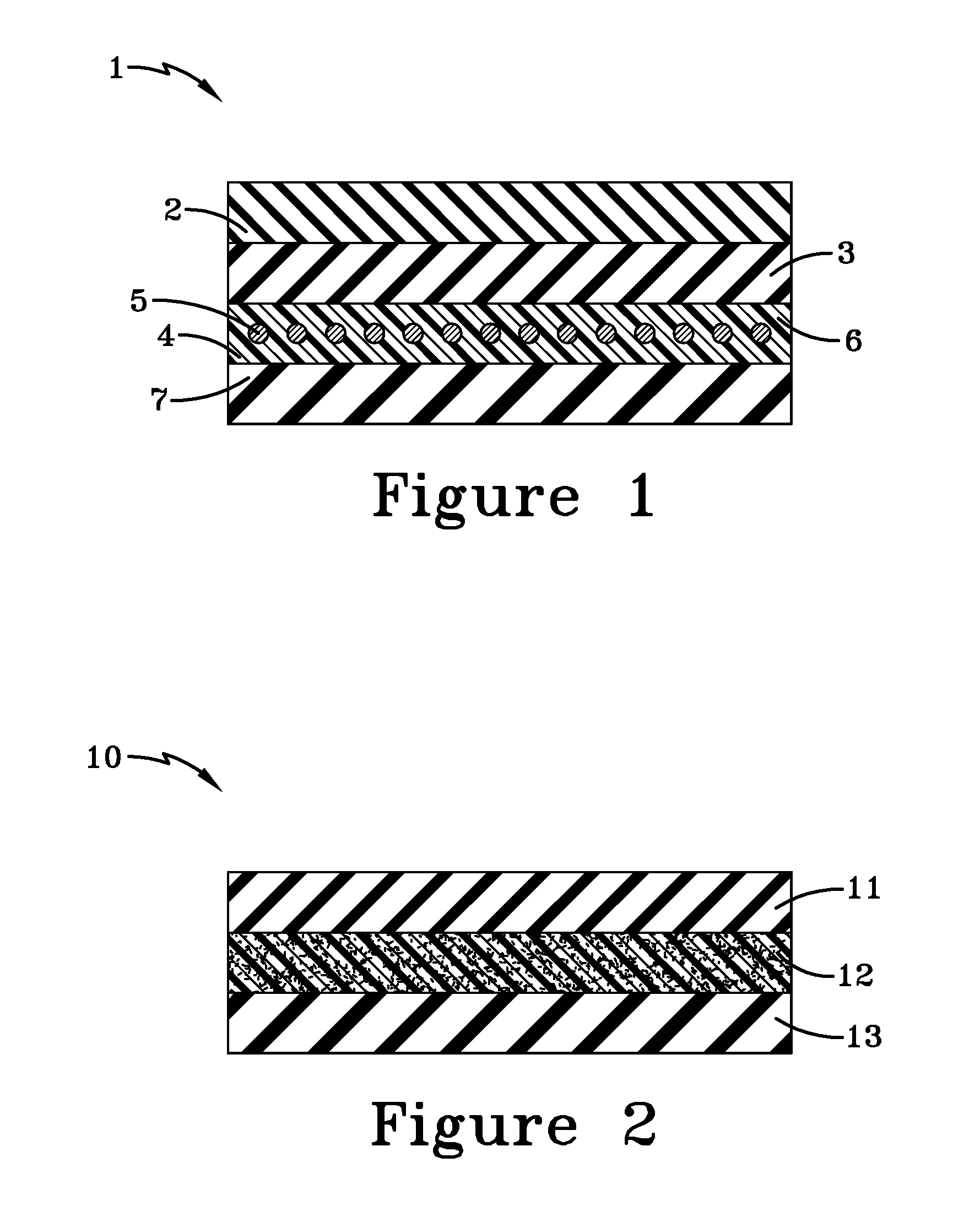
This invention reveals a conveyor belt which is comprised of a carry cover layer, a tie gum layer which is situated immediately below the carry cover layer, a reinforcement layer which includes steel cords which are embedded in polychloroprene and which is situated immediately below the tie gum layer, and a rubber layer which is situated immediately below the reinforcement layer, wherein the carry cover layer is comprised of a millable urethane rubber. The tie gum layer will typically be an alloy of polyvinylchloride and nitrile rubber to attain good adhesion between the carry cover layer and the reinforcement layer. The subject invention also reveals a conveyor belt which is comprised of a carry cover layer, a reinforcement layer which includes a resorcinol-formaldehyde-latex coated fabric reinforcement, and a rubber layer which is situated immediately below the reinforcement layer, wherein the carry cover layer is comprised of a millable urethane rubber.

Description

[0001]This application claims the benefit of U.S. Provisional Patent Application Ser. No. 61 / 861,472, filed on Aug. 2, 2013. The teachings of U.S. Provisional Patent Application Ser. No. 61 / 861,472 are incorporated herein by reference in their entirety.FIELD OF THE INVENTION[0002]The invention relates to conveyor belts that are highly abrasion resistant and which are particularly useful in mining of minerals and coal by virtue of their excellent resistance to abrasion.BACKGROUND OF THE INVENTION[0003]In a multitude of commercial applications, it is common to employ a heavy-duty conveyor belt for the purpose of transporting product and material. The conveyor belts so employed may be relatively long, for example, on the order of miles, and represent a high cost component of an industrial material handling operation. For instance, conveyor belts are widely used for moving minerals, coal, and a wide variety of manufactured products from one point to another. Heavy duty conveyor belts us...

Claims


Application Information

Patent Timeline
IPC IPC(8): B65G15/36
CPCB65G15/36B65G15/00C08L11/00C08L27/06C08L75/08B32B15/095B32B7/12C08L7/00C08L47/00B32B27/06B32B27/40B65G15/34B32B2307/554B32B2433/02
Inventor BURROWES, THOMAS GEORGESI, MAYU
Owner CONTITECH USA INC
Learn More