Optical fiber glass base material manufacturing method and optical fiber glass base material
a technology of optical fiber glass and base material, which is applied in the direction of manufacturing tools, glass deposition burners, other domestic articles, etc., can solve the problems of low adhesive strength between the starting base material and the second cladding, difficulty in achieving a clear stepped form of refractive index distribution, and difficulty in selectively adding fluorine to only the second cladding portion
- Summary
- Abstract
- Description
- Claims
- Application Information
AI Technical Summary
Benefits of technology
Problems solved by technology
Method used
Image
Examples
embodiment 1
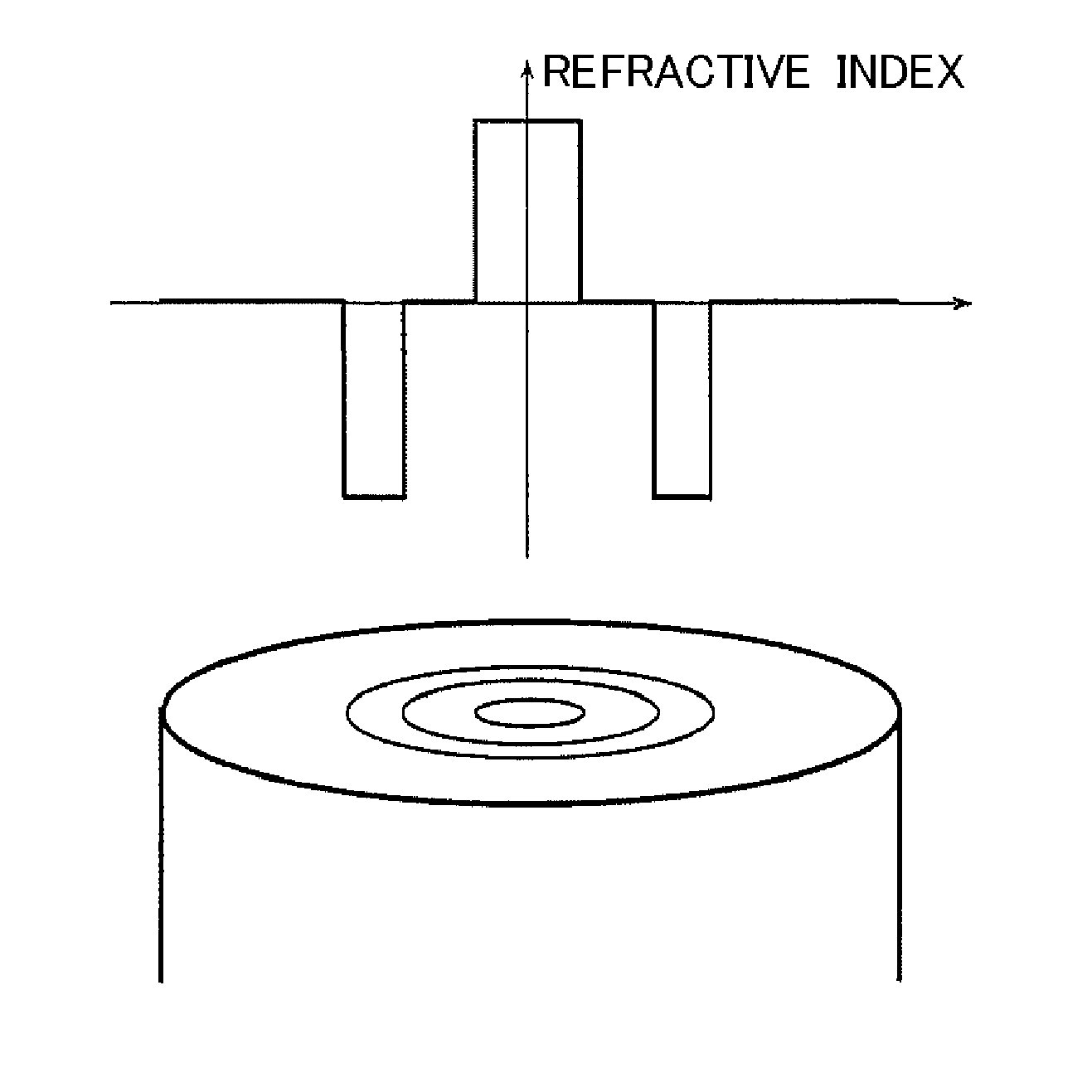
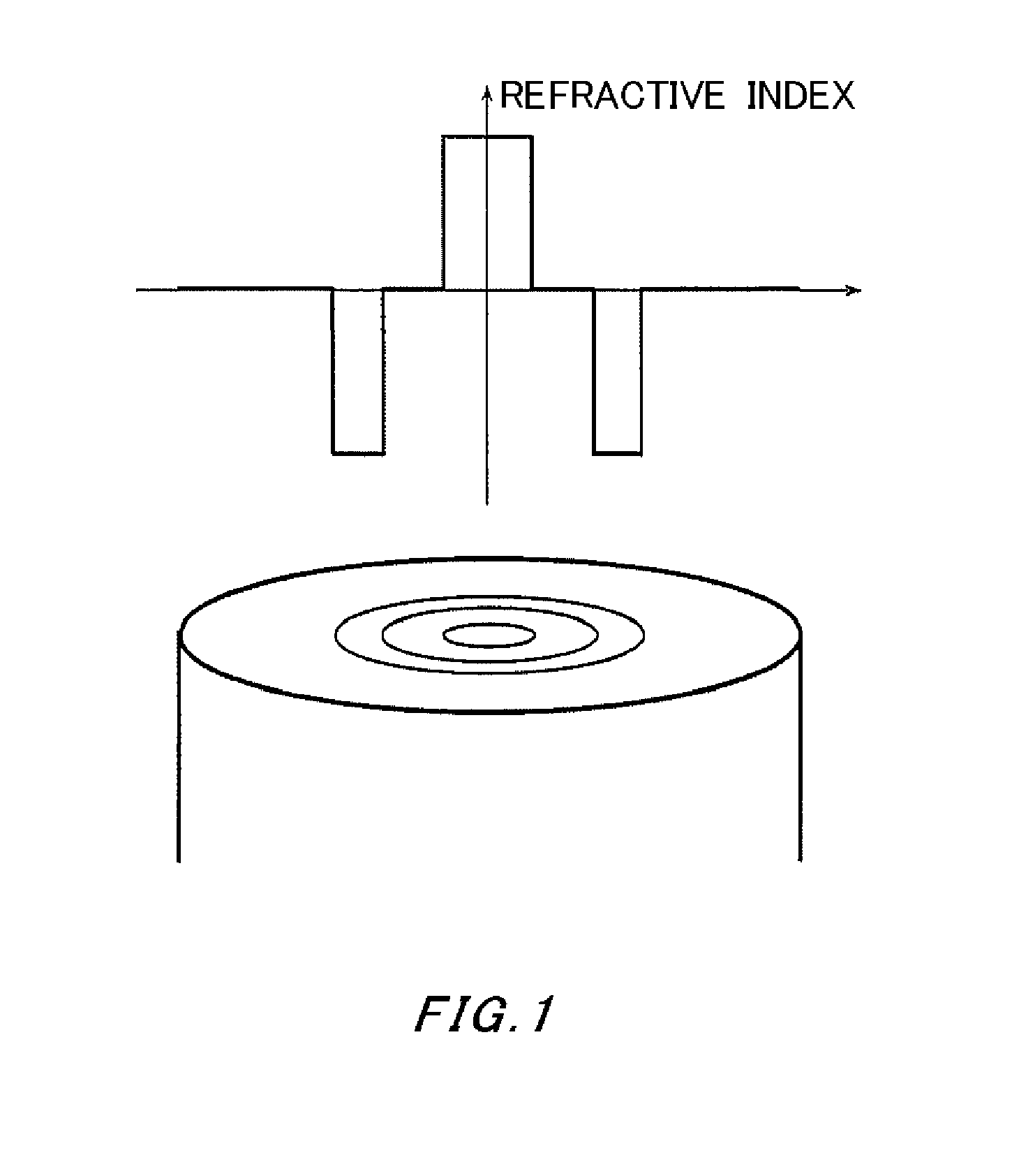
[0030]a porous silica glass base material made of a core and a first cladding was manufactured using VAD, and then underwent a dehydration step, a vitrification step, and an elongating step to manufacture a glass base material with an outer diameter of 39 mm. The core was doped with germanium, and the first cladding was pure silica glass. A portion with a thickness of 2 mm was removed from the surface of the glass base material through wet etching, and the resulting starting base material had an outer diameter of 35 mm and a length of 600 mm. While rotating this starting base material using the core as the axis, a burner arranged facing the axis at a right angle was supplied with hydrogen at a flow rate of 50 L / min and oxygen at a flow rate of 25 L / min to produce an oxyhydrogen flame, and flame polishing was performed by moving this burner back and forth in a direction parallel to the starting base material at a speed of 90 mm / min.
[0031]After this, the porous glass layer of the seco...
embodiment 2
[0034]Using the same method as in Embodiment 1, a starting base material was formed including a core and a first cladding and having an outer diameter of 35 mm and a length of 600 mm. The core was doped with germanium, and the first cladding was pure silica glass. Flame polishing of the starting base material was performed by supplying a burner with hydrogen at a flow rate of 50 L / min and oxygen at a flow rate of 25 L / min to produce an oxyhydrogen flame and moving this burner back and forth for one pass at a speed of 50 mm / min. After this, the porous glass layer of the second cladding was deposited on the starting base material using OVD. The gas conditions for the first deposition pass immediately after the beginning of the raw material supply were set to be a hydrogen flow rate of 70 L / min and an oxygen flow rate of 44 L / min. This hydrogen flow rate is 32% greater than the normal flow rate of 53 L / min.
[0035]The gas conditions were such that the hydrogen flow rate from the second d...
embodiment 3
[0036]Using the same method as in Embodiment 1, a starting base material was formed including a core and a first cladding and having an outer diameter of 32 mm and a length of 600 mm. The core was doped with germanium, and the first cladding was pure silica. In the same manner as in Embodiment 1, flame polishing of the surface of the starting base material was performed by supplying a burner with hydrogen at a flow rate of 50 L / min and oxygen at a flow rate of 25 L / min to produce an oxyhydrogen flame and moving this burner back and forth for one pass at a speed of 90 mm / min. After this, the porous glass layer of the second cladding was deposited on the starting base material using OVD. The hydrogen flow rate for the first deposition pass immediately after the beginning of the raw material supply was set to 70 L / min, which is 32% greater than the flow rate under normal conditions. The oxygen flow rate was set to 44 L / min, which is the normal condition.
[0037]The hydrogen flow rate fro...
PUM
| Property | Measurement | Unit |
|---|---|---|
| diameter | aaaaa | aaaaa |
| density | aaaaa | aaaaa |
| density | aaaaa | aaaaa |
Abstract
Description
Claims
Application Information
 - R&D
- Intellectual Property
- Life Sciences
- Materials
- Tech Scout
- Unparalleled Data Quality
- Higher Quality Content
- 60% Fewer Hallucinations
Browse by: Latest US Patents, China's latest patents, Technical Efficacy Thesaurus, Application Domain, Technology Topic, Popular Technical Reports.
© 2025 PatSnap. All rights reserved.Legal|Privacy policy|Modern Slavery Act Transparency Statement|Sitemap|About US| Contact US: help@patsnap.com


