Eureka AIR delivers breakthrough ideas for toughest innovation challenges, trusted by R&D personnel around the world.

Pump system for gas dehydrator powered by thermal electric generator

Inactive Publication Date: 2015-02-12
KOLD KATCHER
View PDF7 Cites 1 Cited by
  • Summary
  • Abstract
  • Description
  • Claims
  • Application Information

AI Technical Summary

Benefits of technology

The invention is a pump system and method for pumping fluid through a gas dehydration system. The system includes an absorber for removing water from the gas and a reboiler for regenerating the fluid. The pump system includes a first gear pump connected to the absorber and the reboiler for pumping the regenerated fluid. The system also includes an electric motor for driving the first gear pump. The pump system can be retrofitted into an existing gas dehydration system. The technical effect of the invention is to provide a more efficient and effective pump system for gas dehydration.

Problems solved by technology

In the natural gas industry, recovered natural gas from a production well generally contains a large amount of water mixed in with the gas, which can create problems during recovery and processing of the gas.
Specifically, the water may freeze in pipelines and equipment, and / or form hydrates with carbon dioxide and hydrocarbons, which may result in plugging equipment and pipelines.
The water often contains acid gas such as hydrogen sulfide (H2S) and carbon dioxide (CO2), that may liquefy and drop out as the temperature or pressure of the gas decreases, thereby causing corrosion in equipment and pipelines.
One particular problem associated with glycol dehydration processes is the requirement to dehydrate natural gas at locations where grid power is not available.
A Kimray™ pump uses high pressure gas from the reservoir to drive a piston motor to pressurize the dry glycol, However Kimray™ pumps rely on high pressures to drive the pump, and thus they often stall or run erratically when there is reduced reservoir pressure, such as 200 psig or lower.

Method used


Image

  • Pump system for gas dehydrator powered by thermal electric generator
  • Pump system for gas dehydrator powered by thermal electric generator
  • Pump system for gas dehydrator powered by thermal electric generator

Examples


Embodiment Construction

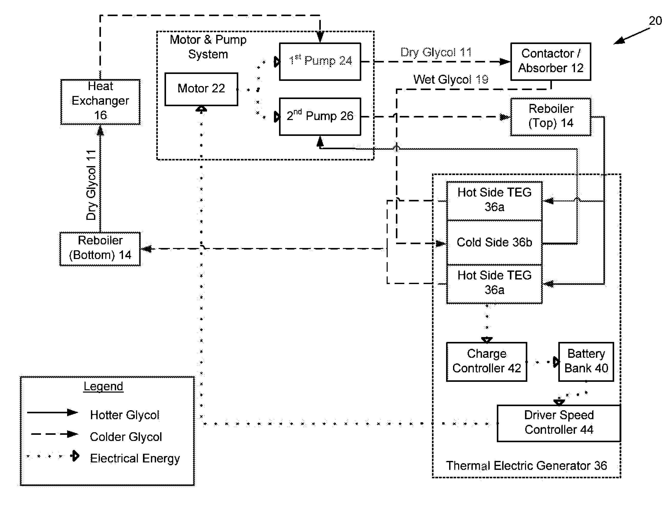
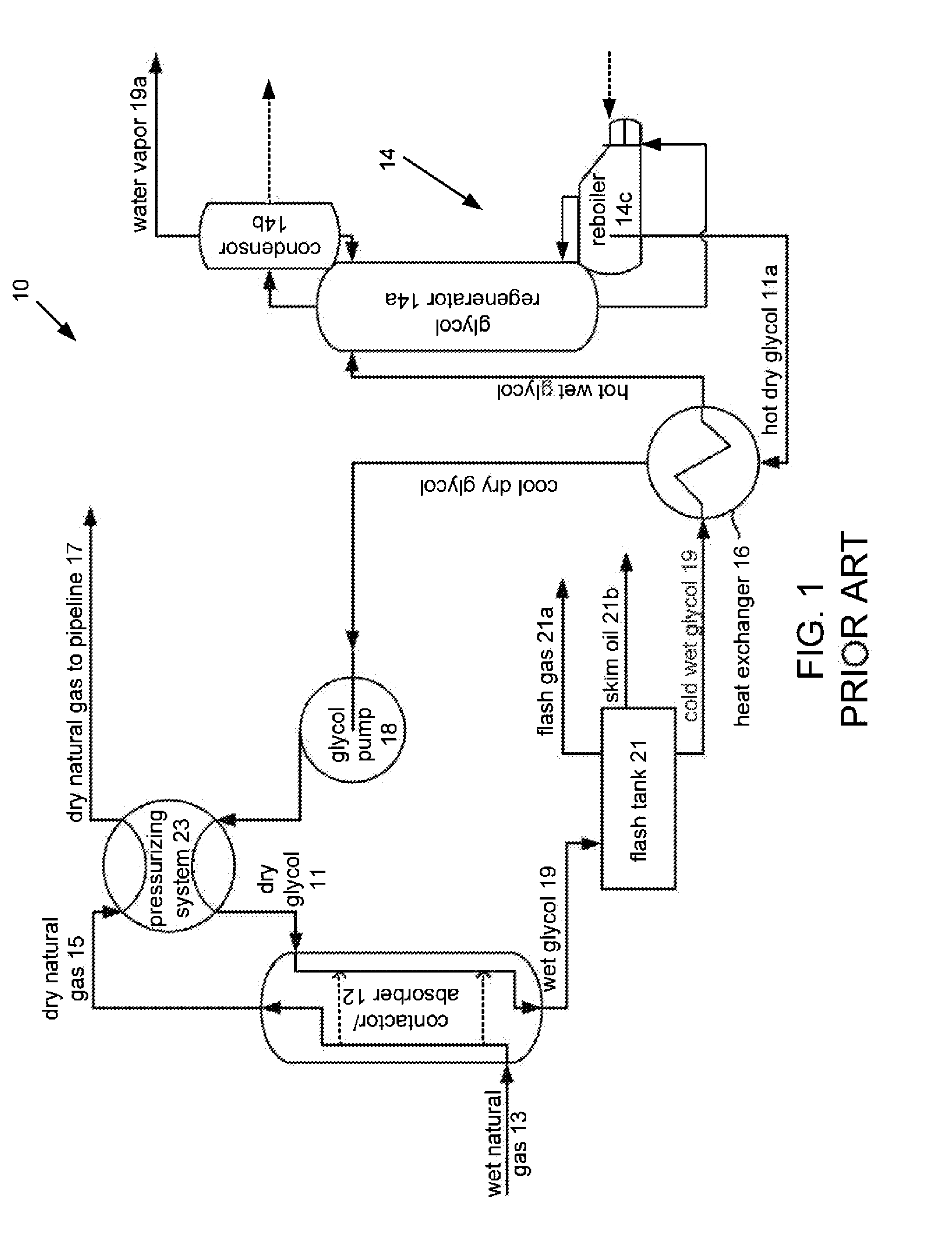
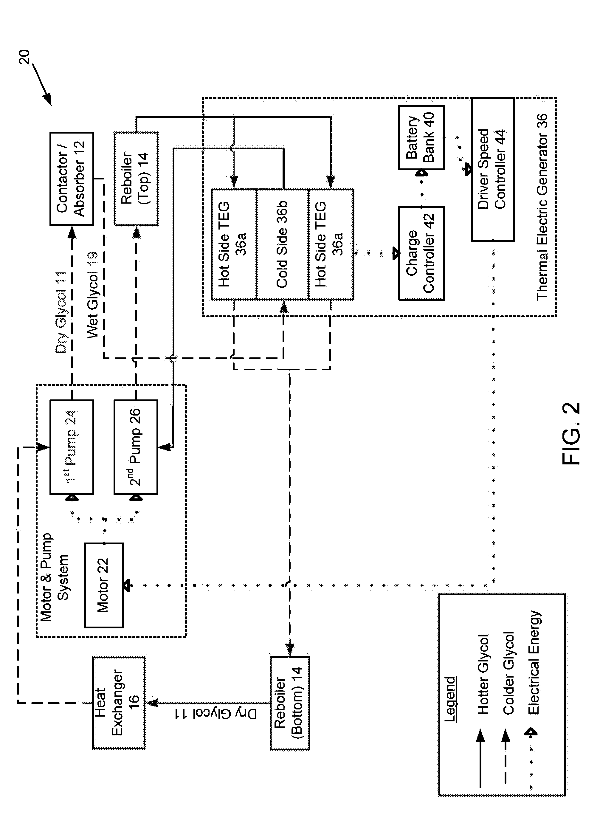
[0039]With reference to the figures a pump system 20 for use in a gas dehydration system 10 is described. Referring to FIG. 2, the pump system 20 generally comprises a motor 22, a first pump 24, a second, pump 26, a thermal electric generator 36 and a battery bank 40. The pump system 20 is plumbed into a typical gas dehydration system 10, such as the one shown in FIG. 1 and described in the background of the invention, which generally includes the absorber 12, reboiler 14, heat exchanger 16 and glycol pump 18.

[0040]In one embodiment, the motor 22 of the pump system 20 drives the first and second pumps 24, 26. Preferably, the motor is an electric motor connected to a belt drive for synchronously driving the first and second pumps 24, 26 using a belt and pulley system or other means (not shown). In one embodiment, the pumps are hydraulic gear pumps and the motor is a variable speed motor, such as a 24 volt DC electric motor. The speed of the motor is controlled automatically or manual...


PUM

PropertyMeasurementUnit
Temperatureaaaaaaaaaa
Pressureaaaaaaaaaa

Abstract

A pump system for use in a gas dehydration system having an absorber / contactor and a reboiler is used to pump glycol or another fluid through a natural gas dehydration system. The pump system includes a gear pump connected to an electric motor for pumping glycol from the reboiler to the contactor / absorber, The motor may be powered by a thermoelectric generator that uses temperature differences in the gas dehydration system fluid to convert heat into electric energy, The pump system may also include additional pumps for moving fluid from the absorber to the reboiler, for moving a second fluid through a heat trace loop, and / or for driving peripheral components.

Description

CROSS-REFERENCE TO RELATED APPLICATIONS[0001]This application claims priority to U.S. Provisional Patent Application No. 61 / 864,866 filed on Aug. 12, 2013, the entire disclosure of which is incorporated herein by reference.FIELD OF THE INVENTION[0002]The invention relates to an electric pump system powered by a thermal electric generator for use in a gas dehydration system.BACKGROUND OF THE INVENTION[0003]In the natural gas industry, recovered natural gas from a production well generally contains a large amount of water mixed in with the gas, which can create problems during recovery and processing of the gas. Specifically, the water may freeze in pipelines and equipment, and / or form hydrates with carbon dioxide and hydrocarbons, which may result in plugging equipment and pipelines. The water often contains acid gas such as hydrogen sulfide (H2S) and carbon dioxide (CO2), that may liquefy and drop out as the temperature or pressure of the gas decreases, thereby causing corrosion in ...

Claims


Application Information

Patent Timeline
IPC IPC(8): F04B35/04B01D53/26
CPCB01D53/26F04B35/04F04C11/00B01D53/263Y10T29/49238F04B41/00
Inventor MACPHERSON, DUNCANJACOBI, TERRY
Owner KOLD KATCHER
Why Eureka
Eureka Blog
Learn More