Dilute chemical reaction process

a chemical reaction and dilution technology, applied in the field of dilution chemical reaction process, can solve the problems of serious constraints on the industry, serious reduction of product purity, and low concentration of certain reactions, and achieve the effects of reducing the volume of solvent used, reducing the quantity of solvent, and high reaction yield

Inactive Publication Date: 2015-02-19
VLAAMSE INSTELLING VOOR TECHNOLOGISCH ONDERZOEK NV VITO
View PDF2 Cites 6 Cited by
  • Summary
  • Abstract
  • Description
  • Claims
  • Application Information

AI Technical Summary

Benefits of technology

[0021]The diluting substrate feed system enables the controlled supply of a substrate-solvent mixture having a low substrate concentration, fairly independently of what the substrate concentration is in the feed solution, which may be significantly higher. Because the high substrate dilution is only applied to the substrate volume which is actually supplied to the reactor, reactions which require high dilution of one or more to the substrates or reactants may be carried out using substantially reduced quantities of solvent, while relatively high reaction yields

Problems solved by technology

Industry is often faced with the problem that certain reactions must be carried out at low concentration and/or high dilution of one or more of the substrates.
Indeed, too high substrate concentrations in this type of reactions favour intermolecular reactions and lead to polymerisation of the substrate in the reaction medium or to the occurrence of other unwanted side-reactions, thereby seriously decreasing the yield to the desired product and the product purity.
High substrate dilution however involves the use of large amounts of solvent.
This entails serious

Method used


Image

  • Dilute chemical reaction process
  • Dilute chemical reaction process
  • Dilute chemical reaction process

Examples


example 1

[0100]

[0101]The reaction shown in Scheme 1 is a model Mitsunobu lactonization to form a 13-membered ring.

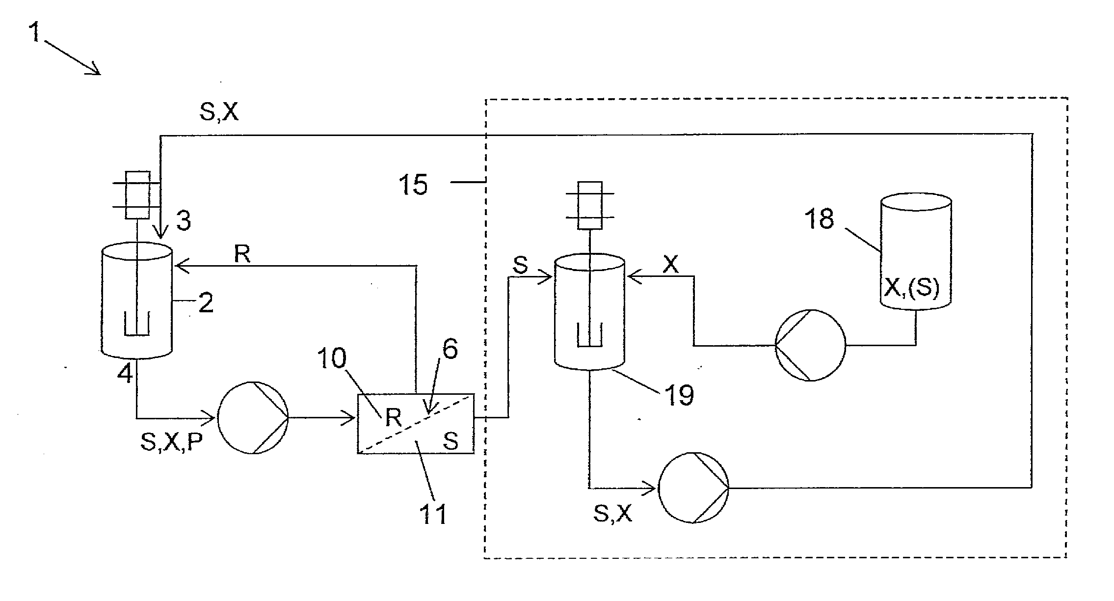
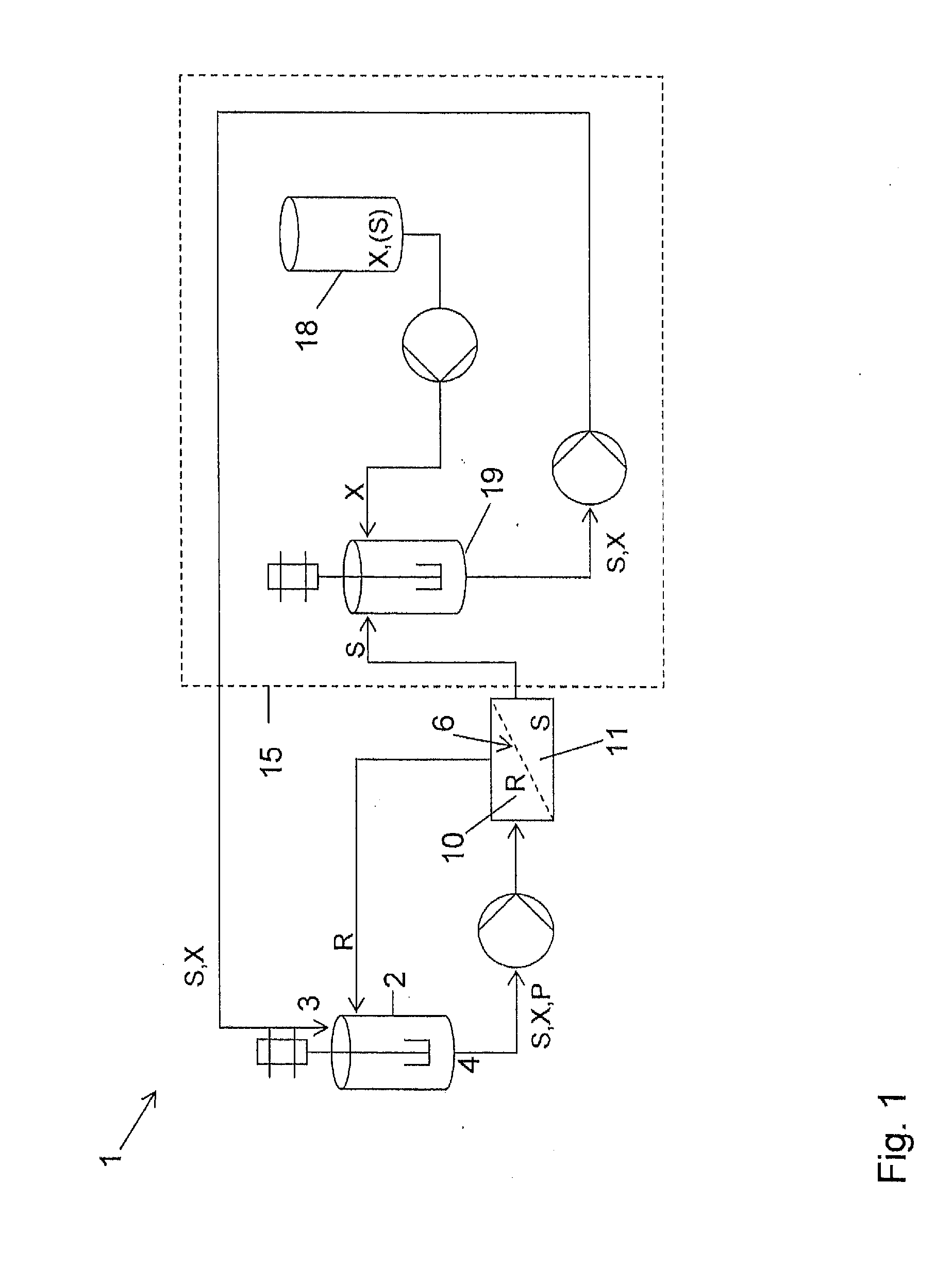
[0102]The ring open precursor to cyclisation had a molecular mass of 595.75 g / mol and the lactone product had a molecular mass of 577.73 g / mole. A chemically cross-linked polyimide membrane (DuraMem™-200, Evonik-MET UK) was used to perform the in-situ solvent recovery (first membrane 6). The rejection of the substrate and product were both 99% and the reagents used to perform the Mitsunobu lactonization had a rejection of 99%.

[0103]The reaction was carried out as follows, using the equipment shown in FIG. 1. To a solution of triphenylphosphine (10.7 g) in dichloromethane (272 ml) under an atmosphere of nitrogen and cooled to 0° C. was added drop wise diisopropylazodicarboxylate (DIAD, 8.25 g) and the resulting mixture was stirred at 0° C. for 30 minutes. This solution was then added to the filtration loop feed tank, featuring in this experiment as reactor (2). The loop had been f...

example 2

[0106]The same reaction was carried out as follows, using the equipment shown in FIG. 1. To a solution of triphenylphosphine (10.7 g) in dichloromethane (272 ml) under an atmosphere of nitrogen and cooled to 0° C. was added drop wise diisopropylazodicarboxylate (DIAD, 8.25 g) and the resulting mixture was stirred at 0° C. for 30 minutes. This solution was then added to the filtration loop feed tank featuring here as the reactor (2). The loop had been fitted with a filtration cell containing a pre-conditioned DuraMem™ 200 membrane.

[0107]The solution in the filtration loop was subjected to constant volume diafiltration using a solution of lactonization starting material (1.49 g) dissolved in dichloromethane (500 ml) in mixing tank (19). The concentration of the starting material in mixing tank (19) was therefore 5 mmolar (200 l / mol). Permeate was recycled into mixing tank (19) and, in order to maintain the concentration of the diafiltration solution, to this was added concentrated lac...

example 3

[0108]The same model reaction was used to demonstrate the principle of this invention using a 0.9 nm TiO2 ceramic membrane (Inopor, Germany) in the equipment shown in FIG. 1. The rejection of the reaction starting material and product were both ≧95% and the reagents used to perform the Mitsunobu lactonization had a rejection of ≧81%.

[0109]To a solution of triphenylphosphine (10.7 g) in dichloromethane (272 ml) under an atmosphere of nitrogen and cooled to 0° C. was added drop wise diisopropylazodicarboxylate (DIAD, 8.25 g) and the resulting mixture stirred at 0° C. for 30 minutes. This solution was then added to the filtration loop feed tank, featuring in this experiment again as reactor (2). The loop had been fitted with a dry membrane.

[0110]The solution in the filtration loop was subjected to constant volume diafiltration using a solution of lactonization starting material (595 mg) dissolved in dichloromethane (500 ml) in mixing tank (19). The concentration of the starting materia...


PUM

PropertyMeasurementUnit
Fractionaaaaaaaaaa
Fractionaaaaaaaaaa
Fractionaaaaaaaaaa

Abstract

Disclosed is a process for carrying out a cyclisation reaction, a polymerization reaction, an enzymatic reaction showing substrate inhibition, an enzymatic reaction showing product inhibition, a reaction showing precipitation of the substrate or of a reactant, the process comprising the steps of
  • a) diluting a fresh substrate with solvent to form a diluted substrate-solvent mixture, and supplying this mixture to a reactor,
  • b) causing the reaction medium in the reactor to react,
  • c) discharging reaction mixture comprising reaction product, solvent, and substrate that has not reacted, to a first filtration membrane which is permeable to the solvent and impermeable to the substrate and to the catalyst or at least one of the reactants,
  • d) returning solvent from the permeate side of the first membrane to dilute the fresh substrate, and
  • e) returning retentate comprising substrate which has not reacted, from the first filtration membrane to the reactor.

Description

FIELD OF THE INVENTION[0001]The present invention relates to an improved process for carrying out a chemical reaction which requires for at least one reason the reaction of a substrate in diluted form, the reaction being a cyclisation reaction, a polymerization reaction, an enzymatic reaction showing substrate inhibition, or a reaction showing precipitation of the substrate or of the reactant.[0002]The process according to the present invention also relates to using a diluting substrate feed system and to a method for supplying substrate to a reaction medium.BACKGROUND OF THE INVENTION[0003]Reacting systems and substrate diluting system of the type described above are in particular intended for use with chemical reactions that are to be carried out with high dilution of the substrate, with concomitant avoidance of low product yield and use of large amounts of solvent.[0004]Industry is often faced with the problem that certain reactions must be carried out at low concentration and / or...

Claims


Application Information

Patent Timeline
IPC IPC(8): C07D267/00C07C67/343C12P13/02B01D61/02B01D61/14
CPCC07D267/00B01D61/025B01D61/027B01D61/147B01D61/145B01D2315/16B01D61/142C12P13/02C07C67/343B01D2311/263B01D61/022B01D61/12Y02P20/582B01D61/029B01D61/149
Inventor BUEKENHOUDT, ANITAVANDEZANDE, PIETERORMEROD, DOMINIQUE
Owner VLAAMSE INSTELLING VOOR TECHNOLOGISCH ONDERZOEK NV VITO
Why Eureka
Try Eureka