Guided photodynamic therapy

a technology of photodynamic therapy and light dose, which is applied in the field of medical equipment for and a method of photodynamic treatment, can solve the problems of difficult to administer the required light dose in a proper fashion, difficult to control and measure the concentration of photosensitizer drugs in the tissue, and unaffected tumor cells

Active Publication Date: 2015-02-26
KONINKLIJKE PHILIPS ELECTRONICS NV
View PDF10 Cites 7 Cited by
  • Summary
  • Abstract
  • Description
  • Claims
  • Application Information

AI Technical Summary

Benefits of technology

[0006]It would be advantageous to provide a PDT system and method capable of precisely controlling light dose administering during treatment.

Problems solved by technology

With PDT it is difficult to control and measure the concentration of the photosensitizer drug in the tissue.
A problem with PDT is that it is difficult to administer the required light dose in a proper fashion.
Too little light will save connective tissue, but also leave tumor cells unaffected, while too much light will lead to damage of connective tissue.
In contrast, external beam (photon and Ion) therapy and brachytherapy leave irreversible permanent damage behind in all tissue, and render tissue boundaries invisible, which is a problem for surgeons in case subsequent surgical resection is planned.
Thus, the method suffers from poor control of the light administering during treatment.

Method used


Image

  • Guided photodynamic therapy
  • Guided photodynamic therapy
  • Guided photodynamic therapy

Examples


Embodiment Construction

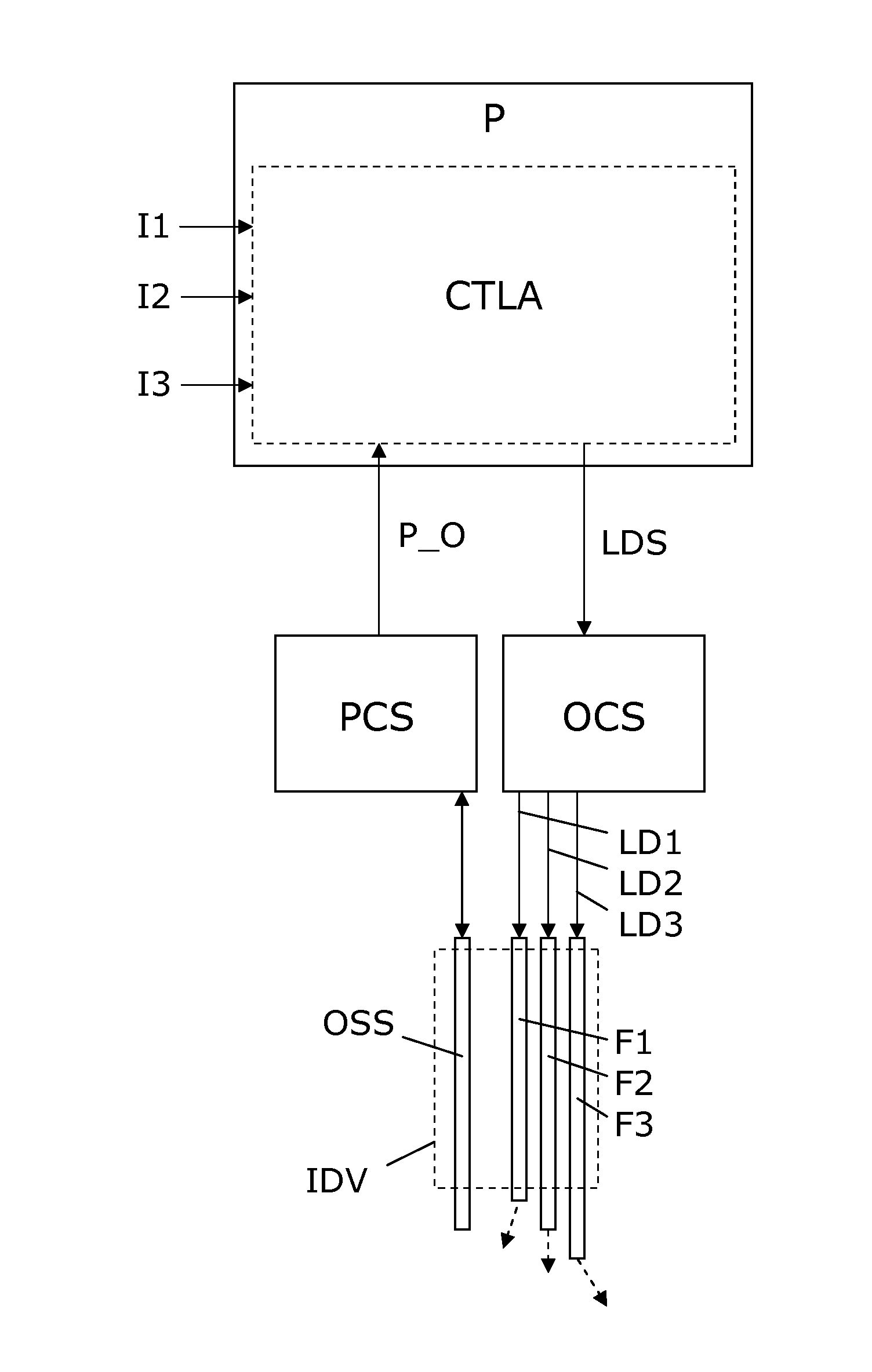
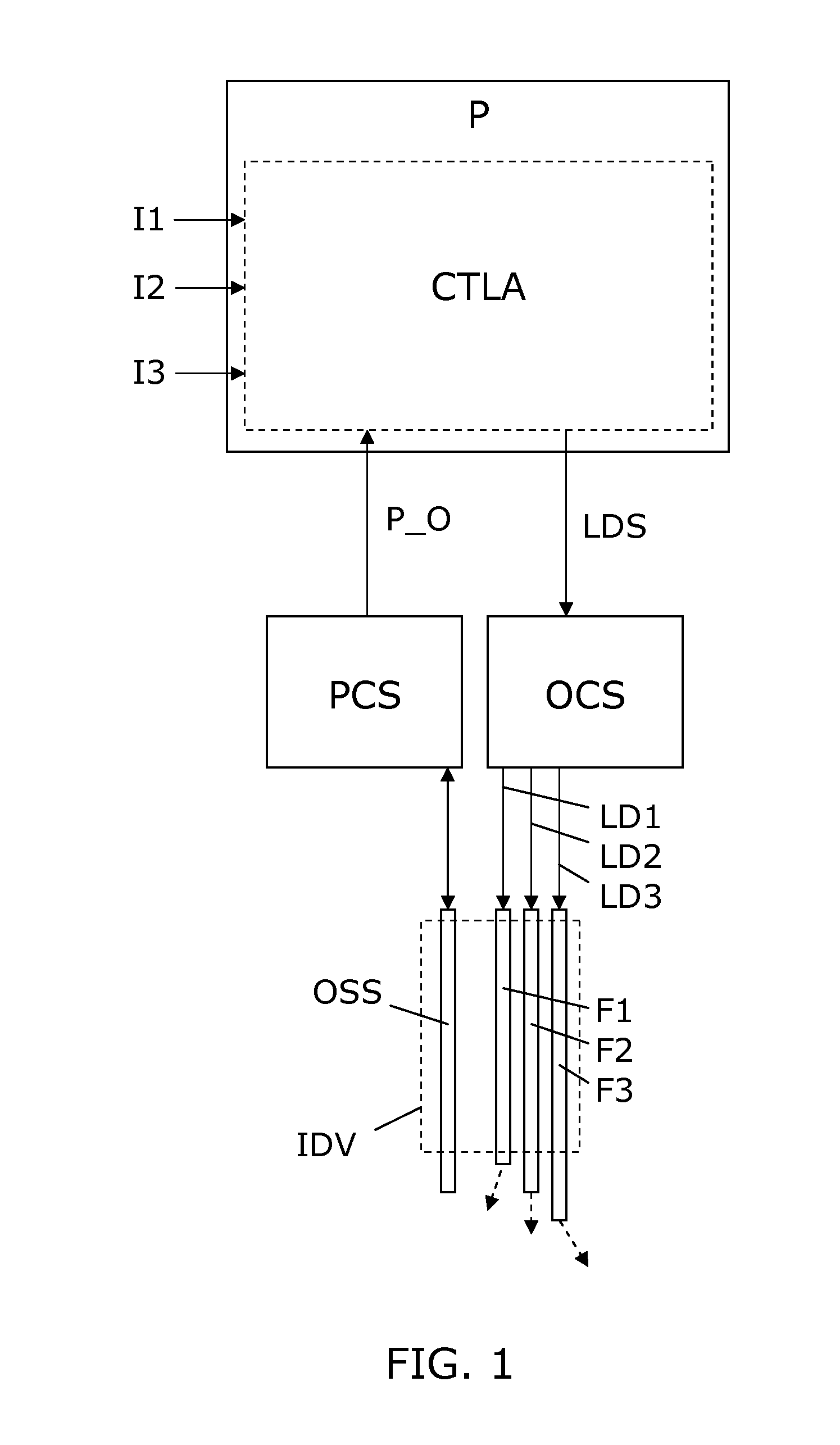
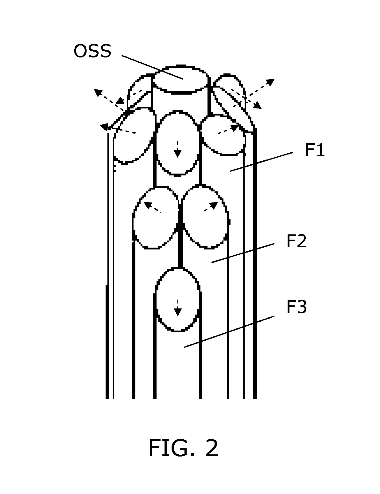
[0050]FIG. 1 illustrates a simple block diagram of a PDT system embodiment according to the invention. An interventional device IDV in the form of an elongated needle, catheter, endoscope or the like, is arranged for insertion into the body, e.g. a tumor, of a patient to be treated with PDT. The interventional device IDV includes a bundle of optical fibers F1-F3 which are individually accessible in one end, and in the opposite end they have fiber ends which serve as light exit ports. The optical fibers F1-F3 are spatially distributed and with fiber ends serving to distribute light in different directions (indicated by dashed arrows) which allows a mix of light from the fiber ends to generate a resulting complex light distribution. For illustration, only 3 fibers F1-F3 are shown, but in practical applications any number of two or more can be used, e.g. 5-10, 10-30, or even more fibers can be used, so as to allow generation of a complex light distribution suited to provide light to a ...


PUM


Abstract

A Photodynamic Therapy (PDT) system with an elongated interventional device (IDV) with a bundle of optical fibers (F1, F2, F3) forming respective light exit ports which can be individually accessed. The bundle has an optical shape sensing fiber (OSS), e.g. including Fiber Bragg Gratings, arranged for sensing position and orientation (P_O) of the light exit ports. A processor executes a control algorithm which generate a light dose signal (LDS) to allow generation of light outputs (LD1, LD2, LD3) to the plurality of optical fibers (F1, F2, F3) accordingly. The control algorithm generates the light dose signal (LDS) in response to the determined position and orientation of the light exit ports (P_O), and three-dimensional body anatomy image information obtained by a first image modality (I1), e.g. X-ray, MRI, CT, ultrasound, or PET-CT. This combination allows precise application of a light dose distribution for PDT treatment of a tumor with a minimal destruction of connective tissue. In embodiments, the control algorithm takes image information regarding distribution of a photo sensitizer in the body tissue (I2) as input. The control algorithm may further take into account image information regarding a concentration of oxygen in the body tissue (I3). Both of such inputs allow a more precise PDT light application.

Description

FIELD OF THE INVENTION[0001]The present invention relates to the field of medical devices or equipment. More specifically, the invention relates to medical equipment for and a method for photodynamic treatment.BACKGROUND OF THE INVENTION[0002]Photodynamic therapy (PDT) treats tumors by a combination of photosensitizer molecules that are preferentially taken up by the tumor cells and illumination with light. The light excites the photosensitizer molecules to become active radicals through the formation of negatively charged singlet oxygen that kills the tumor cells. PDT is a very attractive therapy since it leaves connective tissue intact, while destroying tumor cells.[0003]With PDT it is difficult to control and measure the concentration of the photosensitizer drug in the tissue. The toxic reaction needs the drug, oxygen (tumors are often hypoxic) and light. For providing the drug, there are concepts of oral, intravenous and topical administration (injection into the tumor). A probl...

Claims


Application Information

Patent Timeline
Patent Type & Authority Applications(United States)
IPC IPC(8): A61N5/06G06F19/00A61B19/00G16Z99/00
CPCA61N5/062A61B19/5225A61N2005/063A61N2005/0628G06F19/3437A61N5/0603G02B6/02057G02B6/04G02B6/262A61B90/37A61B2034/2061G16H50/50G16Z99/00
Inventor KUHN, MICHAEL HARALDMUZEL, CHRISTINE CHARLOTTE JUTTAHENDRIKS, BERNARDUS HENDRIKUS WILHELMUSLUCASSEN, GERARDUS WILHELMUS
Owner KONINKLIJKE PHILIPS ELECTRONICS NV
Why Eureka
Try Eureka