Fluorescence microtitre plate reader

a microtitre plate reader and fluorescence technology, applied in the field of fluorescence microtitre plate readers, can solve the problems of unworkable systems, limit the amount of space available in which to construct a viable optical detector system, etc., and achieve the effect of eliminating any noise issues, reducing the distance to image focal length, and reducing the nois

Inactive Publication Date: 2015-03-05
OCULER
View PDF7 Cites 6 Cited by
  • Summary
  • Abstract
  • Description
  • Claims
  • Application Information

AI Technical Summary

Benefits of technology

[0016]Preferably, the camera is a CCD camera, ideally a cooled CCD camera. CCD cameras (chips) are exceptionally sensitive, however they are not always as discerning/selective as other means of optical detection. In particular they are unable to distigush between incident photons and thermal electrons. As a result taking extended exposures, as is necessary in low light, can be subject to excessive noise due to the presence of thermal electrons. In order to mitigate this effect the CCD chip is encased in a quartz vacuum chamber which is connected to a thermoelectric cooling system, this reduces the temperature of the chip to −50° C. below a

Problems solved by technology

This system is unworkable where the test matrix is opaque i.e. milk.
However the packaging of the optics into a

Method used


Image

  • Fluorescence microtitre plate reader
  • Fluorescence microtitre plate reader
  • Fluorescence microtitre plate reader

Examples


example 1

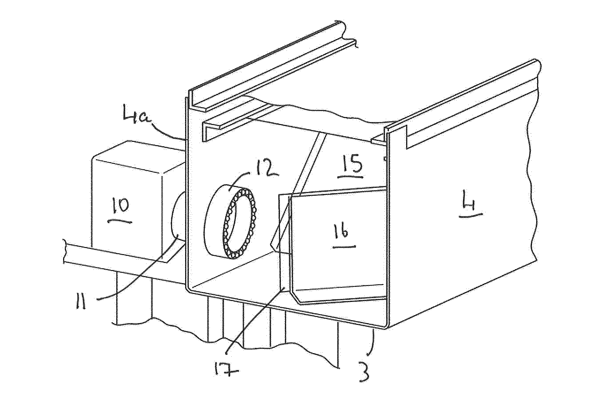
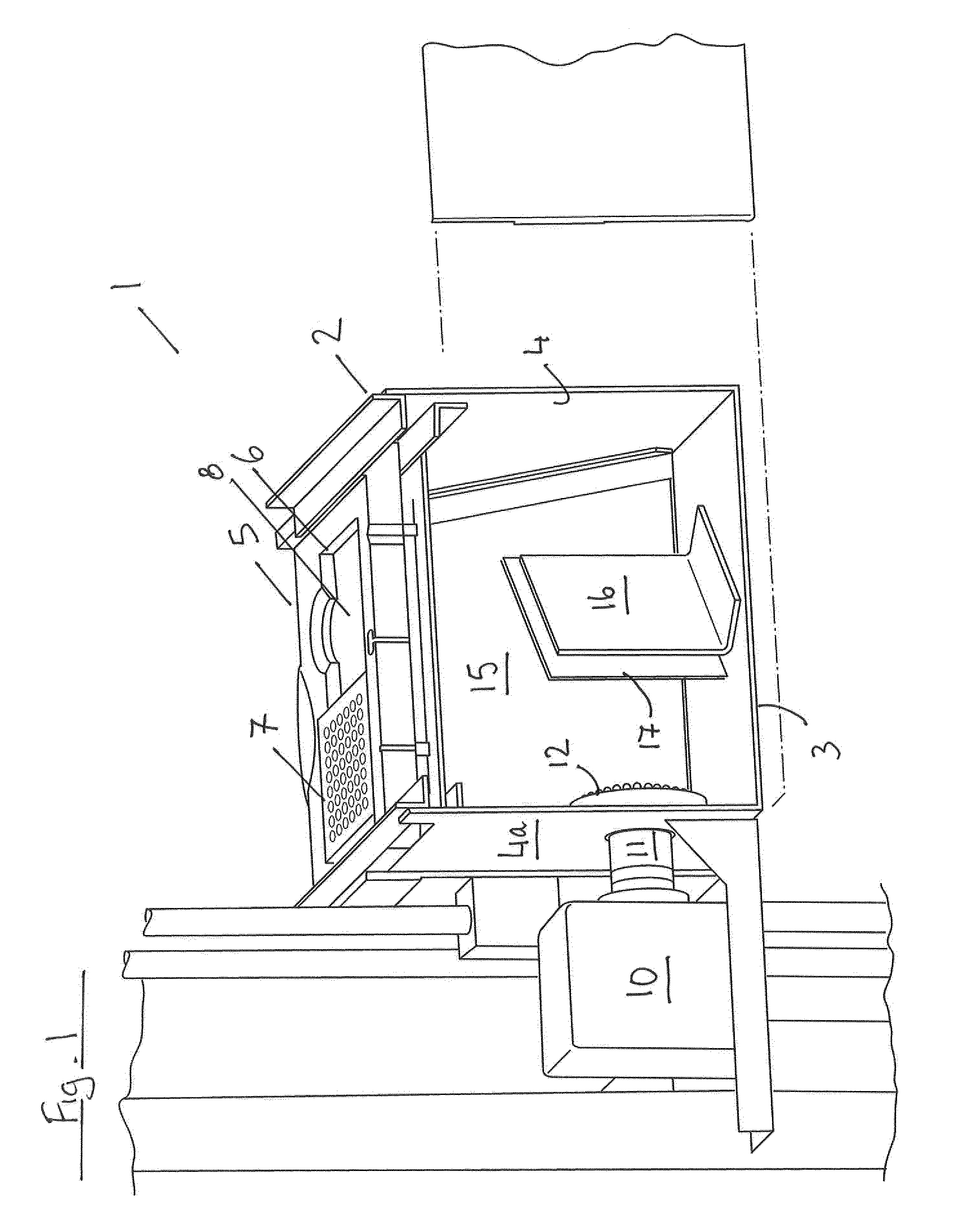
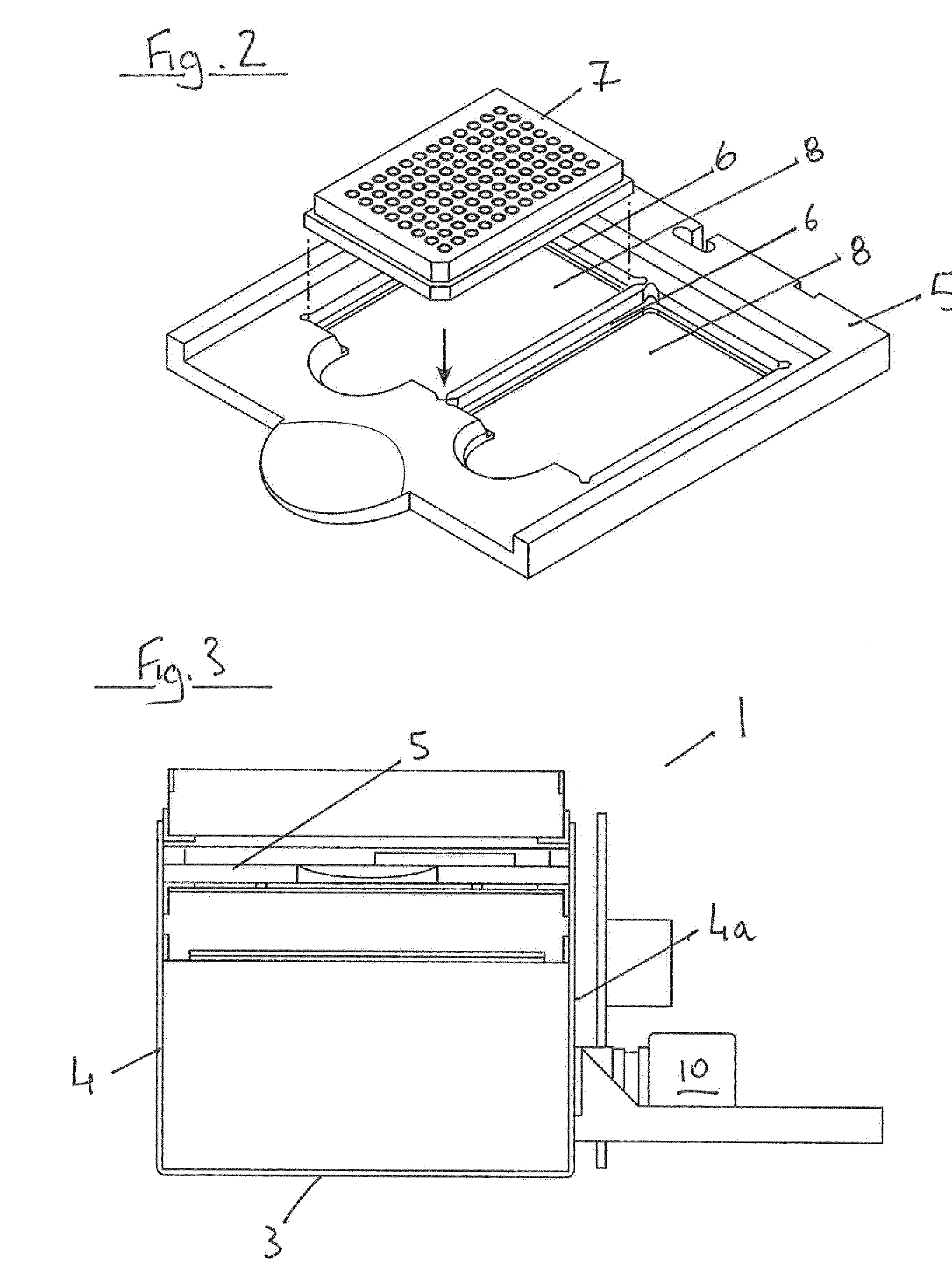
[0070]Referring to the figures, and initially to FIGS. 1 to 4, there is illustrated a fluorescence plate reader according to the invention, indicated generally by the reference numeral 1. The plate reader comprises a body 2 having a base 3, side walls 4 and a top 5 including two seats 6, each of which is adapted to receive a 96-well microtitre plate 7. In FIG. 1, a 96-well microtitre plate 7 is shown seated in one of the seats, and the second seat is not occupied. Each seat 6 defines an aperture 8 which allows light pass from the microtitre plate into and out of the plate reader body.

[0071]An air cooled QSI 616 CCD camera 10 (QSI Imaging) and CF12.5HA-1 fixed focal length lens 11 (Fujinon) are mounted in the sidewall 4a, with an LED ringlight (type-R LED Ringlight sold by SPECBRIGHT) 12 mounted to the sidewall 4a around the lens 11 (see FIG. 4). An optical system is provided in the body 3 to direct illumination light from the LED ringlight 12 to a base of the plate 7 and for directi...

example 2

[0074]A fluorescence plate reader of the invention may be employed to quantify the thermoduric bacterial load of a sample of milk. The process involves an initial step of preparation of the microtitre plate. In this example, a 96 well microtitre plate is employed. Two 200μ aliquots of each sample of milk are taken, and each aliquot applied to a well of the plate. An aliquot of fluorescent dye, Greenlight Dye (Luxel Biosciences Limited), 4× standard proprietary working concenration is added to each well. This dye has an absorption maximum of 380 nm and an emission maximum of 650 nm, thus having a broad stokes shift of 270 nm. Once the milk samples and dye have been added to the plate, mineral oil is added to the top of each well 100 ul.

[0075]The microtitre plate containing the test samples is then placed into a PCR thermocycler device, in this case TECHNE TC-5000, and the device is set to heat the samples to a temperature of 71.7° C. for 15 seconds (or 63° C. for 30 mins) to pasteuri...


PUM


Abstract

A fluorescence microtitre plate reader comprises a plate reader body (2) having a base (3), top (5) and sidewalls (4), the top of the plate reader comprising at least one seat (6) dimensioned for receipt of a microtitre plate (7), the at least one seat defining an aperture (8) in the top of the plate that substantially corresponds to a base of the plate. The plate reader also includes means for illuminating wells of a microtitre plate with light from beneath the plate having an excitation wavelength, and a camera (10) and lens (11) assembly for capturing light emitted by the wells of the microtitre plate and generating a digital image, in which regions of light intensity of the image correspond to wells of the microtitre plate. An optical system is disposed within the plate reader body for expanding the distance to image plane of light, the optical system comprising a first mirror (15) disposed to receive light from the wells of the microtitre plate and reflect the light to second mirror (16) which is disposed to reflect incident light to the camera lens. The means for illumining the wells of the microtitre plate comprises a ring light (12) that embraces the camera and lens assembly.

Description

TECHNICAL FIELD[0001]The invention relates to a fluorescence microtitre plate reader, and a method for detecting fluorescence intensity of light emitted from a well of a microtitre plate.BACKGROUND TO THE INVENTION[0002]Fluorescence microplate readers have been described previously for use in determining aerobic bacterial numbers in samples. These devices generally comprise an optical illumination system and optical detection system that are located on opposite sides of the microplate. Such systems operate on the basis of trans-fluorescense, where the light passes through the sample before being detected. This system is unworkable where the test matrix is opaque i.e. milk. Generally, the detection system for plate readers comprises a photomultiplier tube which is adapted to detect fluorescence intensity of light emitted by a well. Thus, the system requires use of a multiplier tube for each well of the plate, and processing means for collecting data from each photomultiplier tube and...

Claims


Application Information

Patent Timeline
IPC IPC(8): G01N21/64
CPCG01N21/64G01N2201/062G01N2201/06113G01N21/6452G01N21/6456G01N2201/0644
Inventor MOZOLOWSKI, GUYHYNES, JAMES
Owner OCULER
Why Eureka
Try Eureka