Capacitance sensor, acoustic sensor, and microphone

a technology of capacitive sensors and acoustic sensors, applied in the direction of counterbalance, vibration measurement in fluids, solids vibration measurement, etc., can solve the problems of weakness of condenser microphones, reduced size, inferior to mems microphones, etc., to improve the independence of each of the sensing units, wide dynamic range, and low sound pressure

Active Publication Date: 2015-04-16
MMI SEMICON CO LTD
View PDF1 Cites 32 Cited by
  • Summary
  • Abstract
  • Description
  • Claims
  • Application Information

AI Technical Summary

Benefits of technology

[0036]According to the first and second capacitance sensors according to one or more embodiments of the present invention and the third capacitance sensor according to one or more embodiments of the present invention, the vibration electrode plate is divided into a plurality of regions, and a sensing unit configured by the vibration electrode plate and the fixed electrode plate is formed in each of the divided regions. In one or more of the embodiments, since a vibration electrode displaced with a pressure is divided to form a plurality of sensing units, the independence of each of the sensing units is improved.
[0037]An acoustic sensor according to one or more embodiments of the present invention is an acoustic sensor using the first, second, or third capacitance sensor in which a plurality of openings to cause acoustic vibration to pass are formed in the back plate and the fixed electrode plate, and the sensing unit outputs a signal by a change in capacitance bet

Problems solved by technology

However, the electret condenser microphone is weak against heat, and is inferior to a MEMS microphone in corresponding to digitalization, reduction in size, high-functionalization/multi-functionalization, and power saving.
In general, the maximum input sound pressure of a microphone is limited by a total harmonic distortion (Total Harmonic Distortion).
This is because, when sound having a high sound pressure is to be detected with a microphone, harmonic distortion occurs in an output signal to damage sound quality and accuracy.
For this reason, in a high-sensitive microphone that can detect a small volume (low sound pressure), a total harmonic distortion of an output signal increases when the microphone receives sound having a large volume, and, therefore, the maximum detection sound pressure is limited.
This is because the high-sensitive microphone outputs a greater signal and easily causes harmonic distortion.
In contrast to this, when the harmonic distortion of the output signal is reduced to increase the maximum detection sound pressure, the sensitivity of the microphone is deteriorated to make it difficult to detect sound having a small volume with high quality.
As a result, in a general microph

Method used


Image

  • Capacitance sensor, acoustic sensor, and microphone
  • Capacitance sensor, acoustic sensor, and microphone
  • Capacitance sensor, acoustic sensor, and microphone

Examples


first embodiment

Modification of First Embodiment

[0110]FIG. 16 is a plan view showing an acoustic sensor according to a modification of the first embodiment of the present invention, and shows a state in which the back plate 18, the protecting film 30, and the like are removed. As in the acoustic sensor, the diaphragm 13 is completely separated by the slit 17 into the first diaphragm 13a and the second diaphragm 13b, and the first fixed electrode plate 19a and the second fixed electrode plate 19b are integrally connected to each other with a connection unit 64.

second embodiment

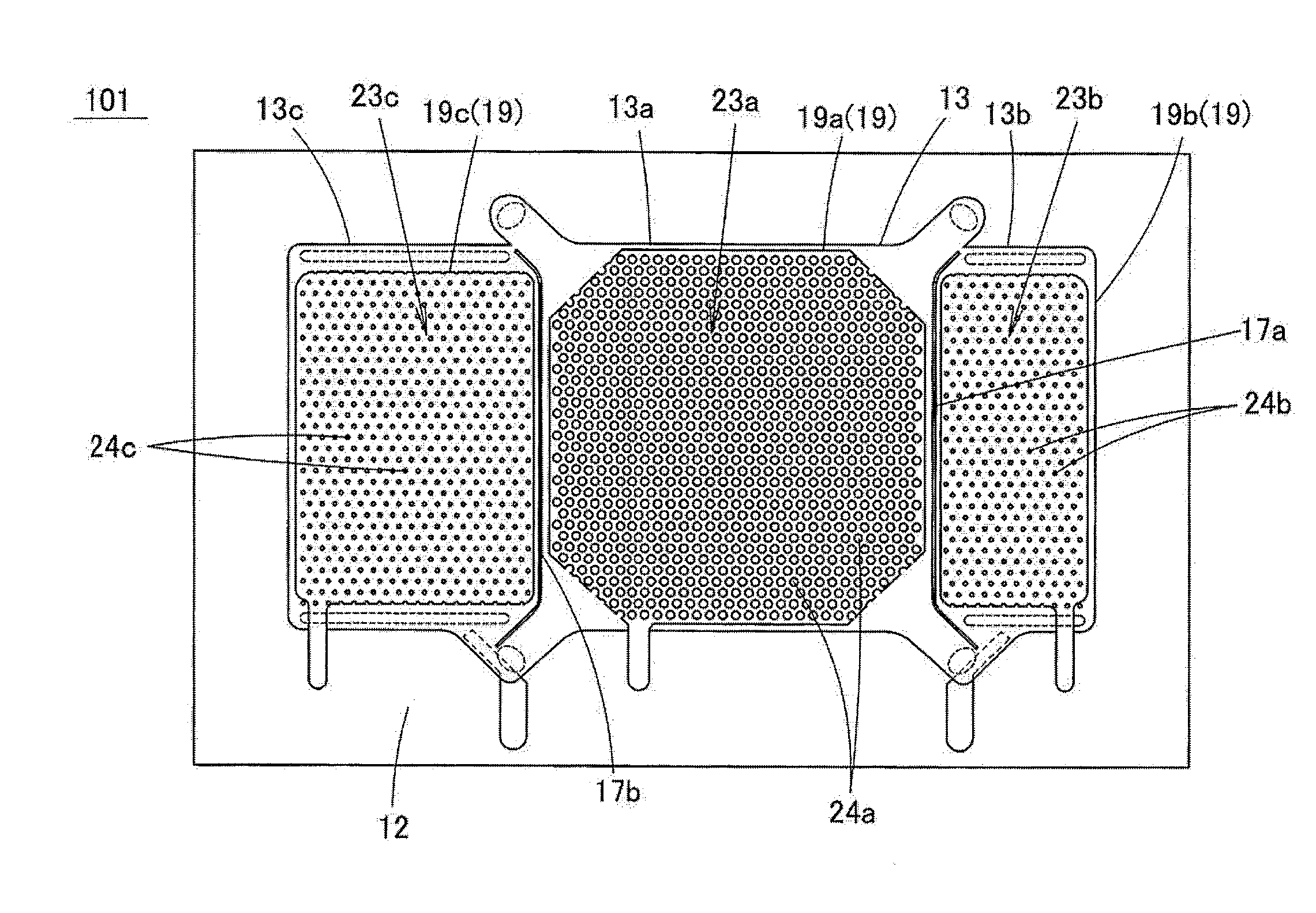
[0111]FIG. 17 is a plan view of an acoustic sensor 71 according to a second embodiment of the present invention. In the acoustic sensor 71, the acoustic holes 24b of the second acoustic sensing unit 23b have a distribution density (number density) lower than that of the acoustic holes 24a of the first acoustic sensing unit 23a. More specifically, an alignment pitch of the acoustic holes 24b is larger than an alignment pitch of the acoustic holes 24a. According to one or more embodiments of the present invention, the alignment pitch of the acoustic holes 24b is twice or more the alignment pitch of the acoustic holes 24a. On the other hand, the hole diameters of the acoustic holes 24a of the first acoustic sensing unit 23a are equal to the hole diameters of the acoustic holes 24b of the second acoustic sensing unit 23b. With respect to points other than the above points, the acoustic sensor 71 has the same structure as that of the acoustic sensor 11 according to the first embodiment, ...

third embodiment

[0115]FIG. 18 is a sectional view of an acoustic sensor 81 according to a third embodiment of the present invention. In the acoustic sensor 81, the thickness of the back plate 18, i.e., a back plate 18b, in the second acoustic sensing unit 23b is larger than the thickness of the back plate 18, i.e., a back plate 18a, in the first acoustic sensing unit 23a. The distribution densities and the hole diameters of the acoustic holes 24a may be equal to the distribution densities and the hole diameters of the acoustic holes 24b. With respect to points other than the above points, the acoustic sensor 71 has the same structure as that of the acoustic sensor 11 according to the first embodiment, and a description thereof will be omitted.

[0116]In the acoustic sensor 81, since the thickness of the back plate 18b is larger than the thickness of the back plate 18a, the rigidity of the back plate 18b in the second acoustic sensing unit 23b is high. As a result, even though the second diaphragm 13b...


PUM


Abstract

A capacitance sensor has a substrate, a vibration electrode plate formed over an upper side of the substrate, a back plate formed over the upper side of the substrate to cover the vibration electrode plate, and a fixed electrode plate arranged on the back plate facing the vibration electrode plate. At least one of the vibration electrode plate and the fixed electrode plate is divided into a plurality of regions. A sensing unit configured by the vibration electrode plate and the fixed electrode plate is formed in each of the divided regions. The plurality of sensing units output a plurality of signals having different sensitivities. At least some sensing units of the sensing units have vibration electrode plates having areas different from the areas of the vibration electrode plates in the other sensing units.

Description

BACKGROUND[0001]1. Technical Field[0002]The present invention relates to a capacitance sensor, an acoustic sensor, and a microphone. More specifically, the present invention relates to a capacitance sensor configured by a capacitor structure including a vibration electrode plate (diaphragm) and a fixed electrode plate. The present invention also relates to an acoustic sensor (acoustic transducer) that converts acoustic vibration into an electric signal to output the electric signal and a microphone using the acoustic sensor. In particular, the present invention relates to a minute-sized capacitance sensor and a minute-sized acoustic sensor that are manufactured by using an MEMS (Micro Electro Mechanical System) technique.[0003]2. Related Art[0004]As a small-sized microphone mounted on a mobile phone or the like, an electret condenser microphone (Electret Condenser Microphone) has been popularly used. However, the electret condenser microphone is weak against heat, and is inferior to...

Claims


Application Information

Patent Timeline
IPC IPC(8): H04R23/00G01H11/00G01R27/26
CPCH04R23/00G01R27/2605G01H11/00H04R2201/003H04R19/005H04R1/28H04R7/06H04R19/04H01L2224/48137H01L2924/15151H01L2924/16152
Inventor UCHIDA, YUKIKASAI, TAKASHI
Owner MMI SEMICON CO LTD
Why Eureka
Try Eureka