
Power-economy mode control system for a vehicle

a power-economy mode and control system technology, applied in the direction of electric control, machines/engines, instruments, etc., can solve the problems of complex system, inability to comprehensively meet the above requirements, and a large amount of inputs for effective functioning, so as to achieve substantial fuel saving, enhance performance, and save fuel

Active Publication Date: 2015-04-23
MAHINDRA & MAHINDRA LTD
View PDF19 Cites 18 Cited by
  • Summary
  • Abstract
  • Description
  • Claims
  • Application Information

AI Technical Summary

Benefits of technology

The invention aims to use existing sensors, actuators, and controllers of the engine and vehicle system to create a custom mode of operation that optimizes fuel efficiency and performance. It also regulates torque delivery for both power and economic mode operation to achieve improved fuel saving. The system does not require any additional components, and drivers can select between economic and power modes using a toggle switch, independent of the accelerator pedal position. The goal is to set the optimum performance from factory settings.

Problems solved by technology

Prior Art discloses several systems but have failed to comprehensively meet the above requirements.
However this system suffers from complexity, it comprises of an electric, a hybrid electric, or a fuel cell vehicle for its operation.
This system disclosed in JP2005214086A suffers from drawbacks such as (i) need of an interfacing unit in between the Engine ECU and Input switch; (ii) Average capability of a vehicle specification at the time of factory shipments; (iii) Switch over from ECO to Normal to Power is dependent on Pedal position; (iv) Factory setting is sub optimal, More complex system, More reliability issues, Safety issues as switching is dependent upon Acceleration Pedal; (v) Use of complex algorisms adding to the failure modes, requires lot many inputs for effective functioning; (vi) Limited to gasoline vehicles, (vii) need of physical Linkages leading more number of parts and in turn reliability issues.
The system disclosed suffers from the drawback that extensive vehicle data (gradient, engine speed, distance to previous vehicle, 1st relative velocity of the previous vehicle, highway main line, maps to limit vehicle rapidly raising phenomena to save the fuel consumption.
This system suffer from the drawback that it needs intricate algorithms involving multiple inputs from various sensors in the vehicle.

Method used


Image

  • Power-economy mode control system for a vehicle
  • Power-economy mode control system for a vehicle
  • Power-economy mode control system for a vehicle

Examples


Embodiment Construction

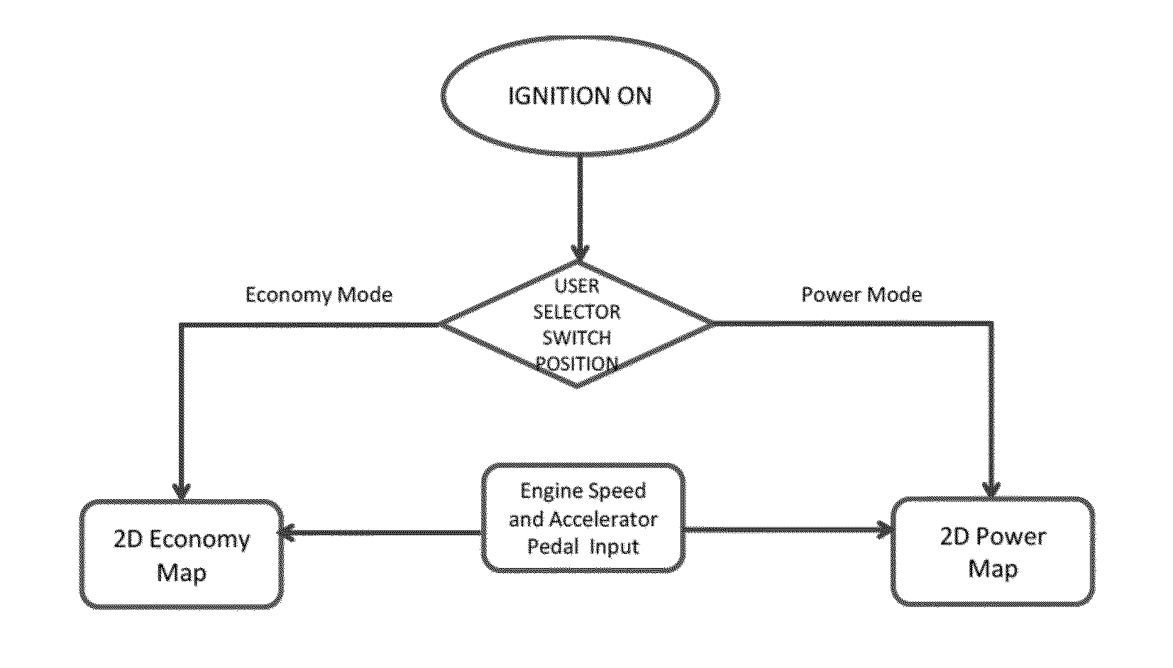
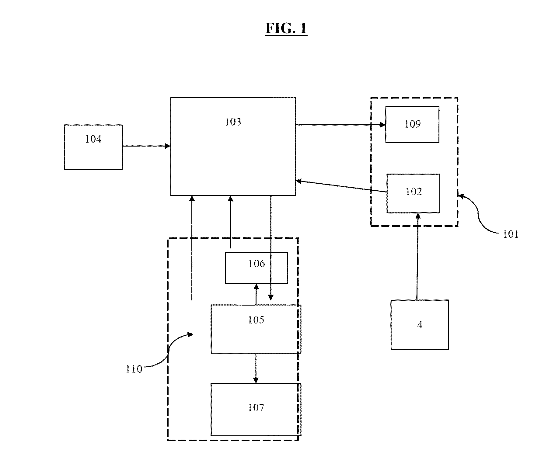
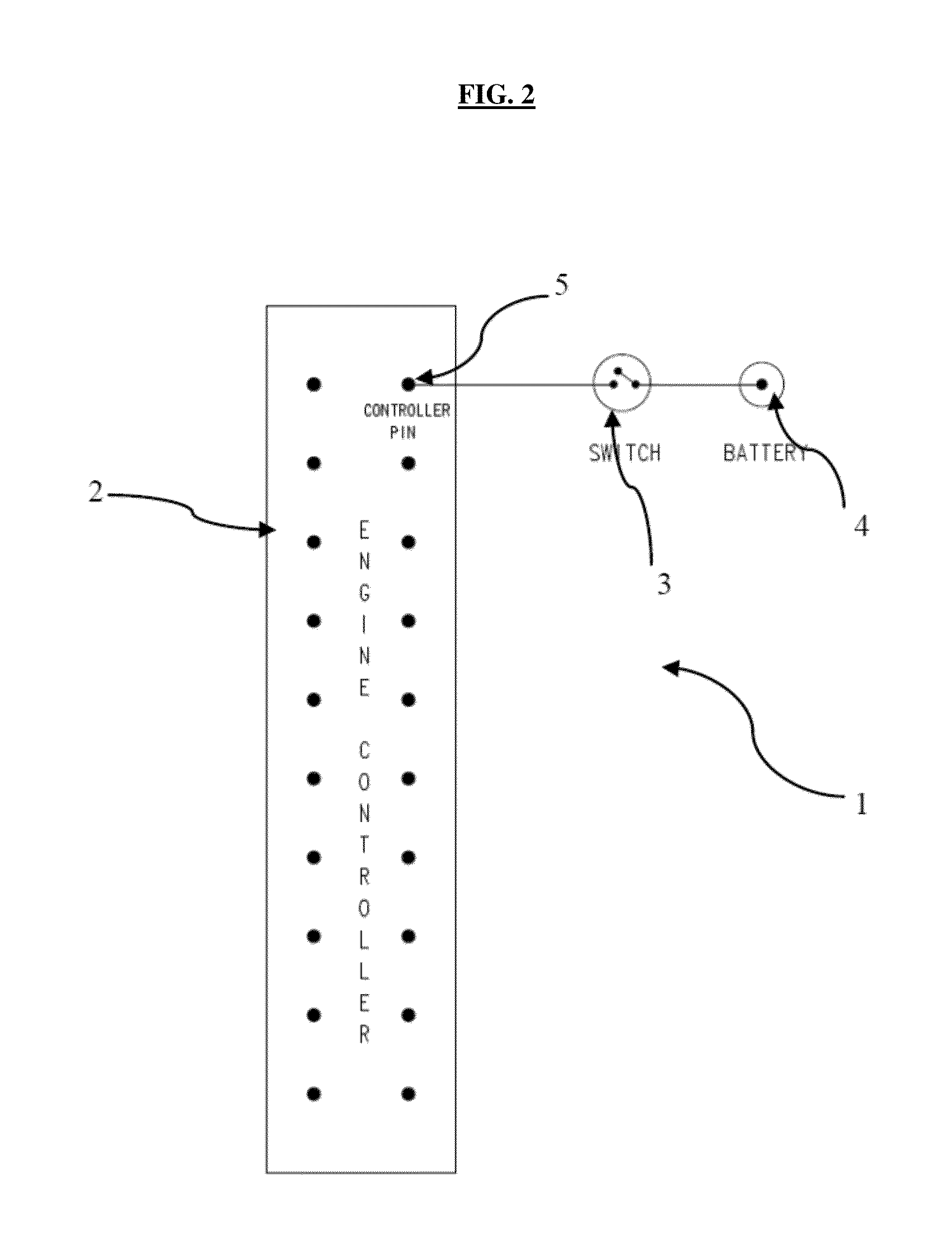
[0038]FIG. 1 illustrates the configuration of the system to enable power and economy mode operations. It comprises of power train 110, electronic control unit 103, mode selection switch 102, accelerator pedal input 104, and mode indication lamp 109. The power train unit 110 comprises of engine 105, engine speed sensor 106 and transmission unit 107. The mode selection switch 102 and indication lamp 109 are adapted to be mounted on the vehicle dashboard instrument panel cluster 101. The said electronic control unit is operably configured with the engine speed sensor 106, engine 105, accelerator pedal mechanism 104 and mode selection switch 102. The driver of the vehicle selects the desired mode (power or economy) by operating the said selection switch 102. The input from the said switch is fed to the said electronic control unit 103 to process it wherein the said unit operates to send a signal to the engine to switch over the mode. The active mode of operation (power / economy) is indic...


PUM


Abstract

The present invention is related to a vehicle provided with operation selection mode. In particular, the present invention is related to a common rail electronically controlled vehicle provided with operation selection mode wherein the user can select either of the power mode and the economy mode of vehicle operation depending on the road conditions. The system of the present invention provides a system to enable selection of power mode operation for power conscious driving requirement or economy mode operation for fuel conscious driving option obviating the use of additional interface devices between engine and engine control unit.

Description

[0001]The present application is a national phase application filed for PCT / IN2013000349 dated 3 Jun. 2013, which claims priority from Indian Application Number 1626 / MUM / 2012, filed on 1 Jun. 2012, the disclosure of which is hereby incorporated by reference herein.TECHNICAL FIELD[0002]The present invention is related to a vehicle provided with operation selection mode. In particular, the present invention is related to a common rail electronically controlled vehicle provided with operation selection mode wherein the user can select either of the power mode and the economy mode of vehicle operation depending on the road and load conditions.BACKGROUND[0003]In the competitive and crowded vehicle market, cost of ownership of the vehicle has become one of the defining selection factors at the consumer end. The effective cost of the vehicle is predominantly dependent on the initial and the operation / running cost of the vehicle. The operational cost is mainly dependents on the fuel consump...

Claims


Application Information

Patent Timeline
Patent Type & Authority Applications(United States)
IPC IPC(8): F02D41/30G07C5/08
CPCF02D41/3064F02D2250/18G07C5/0808F02D41/2422F02D11/105F02D2200/604
Inventor VELUSAMY, RAMASAMYSHAIK, REHAN
Owner MAHINDRA & MAHINDRA LTD
Learn More