Ice and water detection system

a detection system and ice technology, applied in the field of optical systems, can solve the problems of increased vehicle accidents, personal injuries resulting from falls, disruption of transportation and other human activities, and airborne ice conditions that are difficult for pilots to discern, so as to reduce the effects of variations in illumination and refine the determination of cloud droplet siz

Active Publication Date: 2015-04-30
RGT UNIV OF MICHIGAN
View PDF45 Cites 27 Cited by
  • Summary
  • Abstract
  • Description
  • Claims
  • Application Information

AI Technical Summary

Benefits of technology

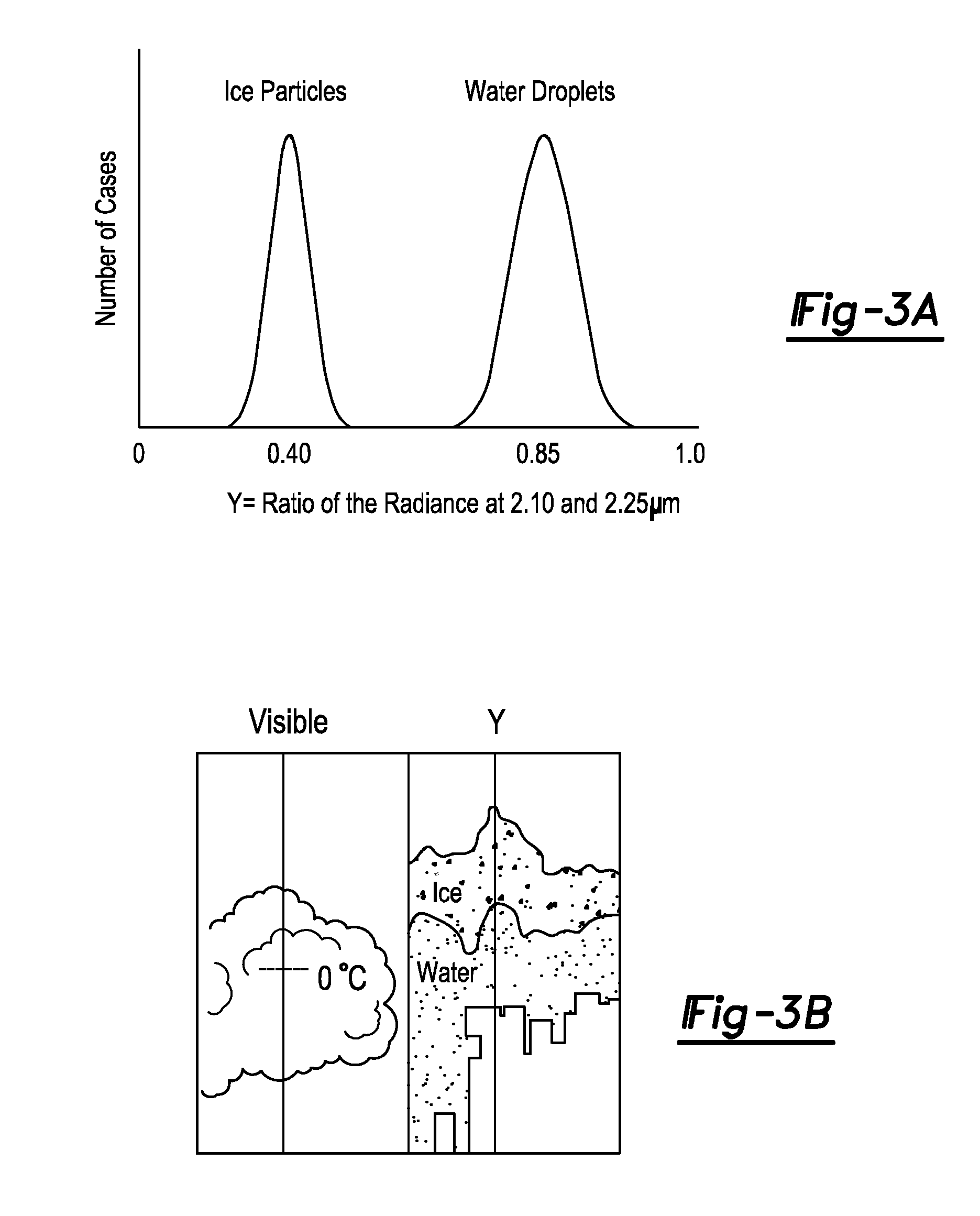
[0048]Turning now to FIG. 4A, a ‘Twomey diagram’ is provided indicating that reflectance values (or radiance values) can be used to determine cloud droplets size. This can be achieved because, at fixed cloud optical thickness (τ), the reflectance at around 2.2 μm (R2.2 μm) decreases with cloud droplet size at the rate oh approximately (k re)1/2, where k is the absorbstion coefficient (the imaginary part of the index of refraction) of water and re is the cloud droplet (effective) radius (Twomey and Seton, 1980). The dependence of cloud reflectance on droplet size is caused by the fact that absorption by liquid water increases relative to scattering with increases in droplet size. For thick clouds, the effect of changes in cloud optical thickness is negligible. Therefore, the relationship between reflectance and cloud droplet radius provided by the ‘Twomey diagram’ is an excellent approximation for thick clouds (clouds of large optical thickness). Measurements at other absorbing

Problems solved by technology

It is well known that either ice or water accumulation on surfaces can increase the number of vehicle accidents, personal injuries resulting from falls, and disruptions in transportation and other human activities.
In connection with vehicle travel, roadway ice can often occur in in ways that are difficult for a prudent driver to detect.
Similarly, in connection with aircraft travel, airborne icing conditions can often occur in ways that are difficult for a pilot to discern.
Unfortunately, few systems exist that are capable of reliably detecting ice or water and providing an associated alert.
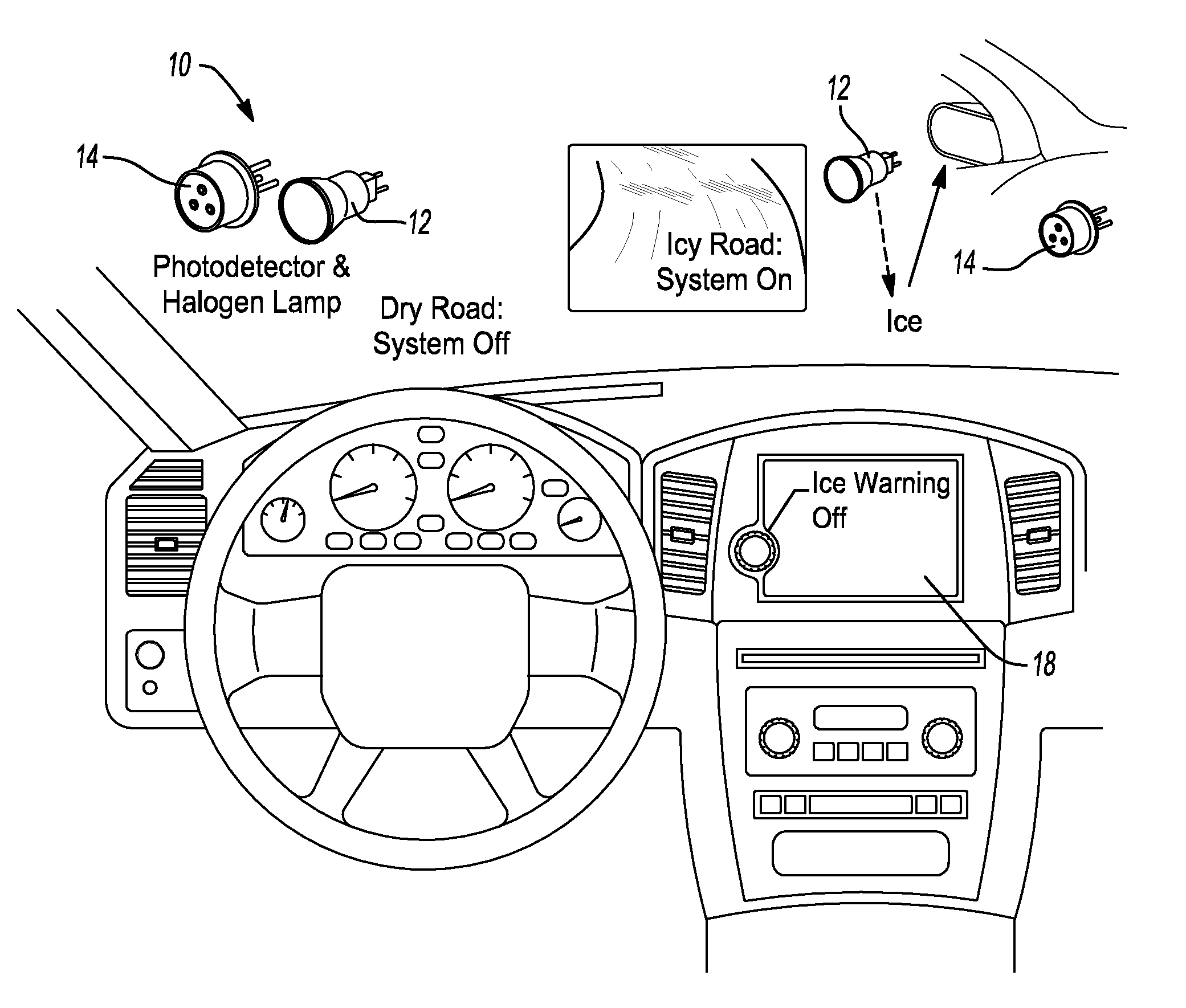
In terms of ground-based vehicles, such as cars, trucks, trains, automated people movers, rails, monorails, metros, buses, motorcycles, bicycles, and similar vehicles, there is a surprising lack of suitable systems for detecting and warning users of the presence of ice or water on surfaces, such as roadways, bridges, railways, sidewalks, or even taxiways (such as in connection with ground operations of aircraft).
However, unfortunately, this is not typically indicative of the presence of s

Method used


Image

  • Ice and water detection system
  • Ice and water detection system
  • Ice and water detection system

Examples


Embodiment Construction

[0035]Example embodiments will now be described more fully with reference to the accompanying drawings. Example embodiments are provided so that this disclosure will be thorough, and will fully convey the scope to those who are skilled in the art. Numerous specific details are set forth such as examples of specific components, devices, and methods, to provide a thorough understanding of embodiments of the present disclosure. It will be apparent to those skilled in the art that specific details need not be employed, that example embodiments may be embodied in many different forms and that neither should be construed to limit the scope of the disclosure. In some example embodiments, well-known processes, well-known device structures, and well-known technologies are not described in detail.

[0036]The terminology used herein is for the purpose of describing particular example embodiments only and is not intended to be limiting. As used herein, the singular forms “a,”“an,” and “the” may b...


PUM


Abstract

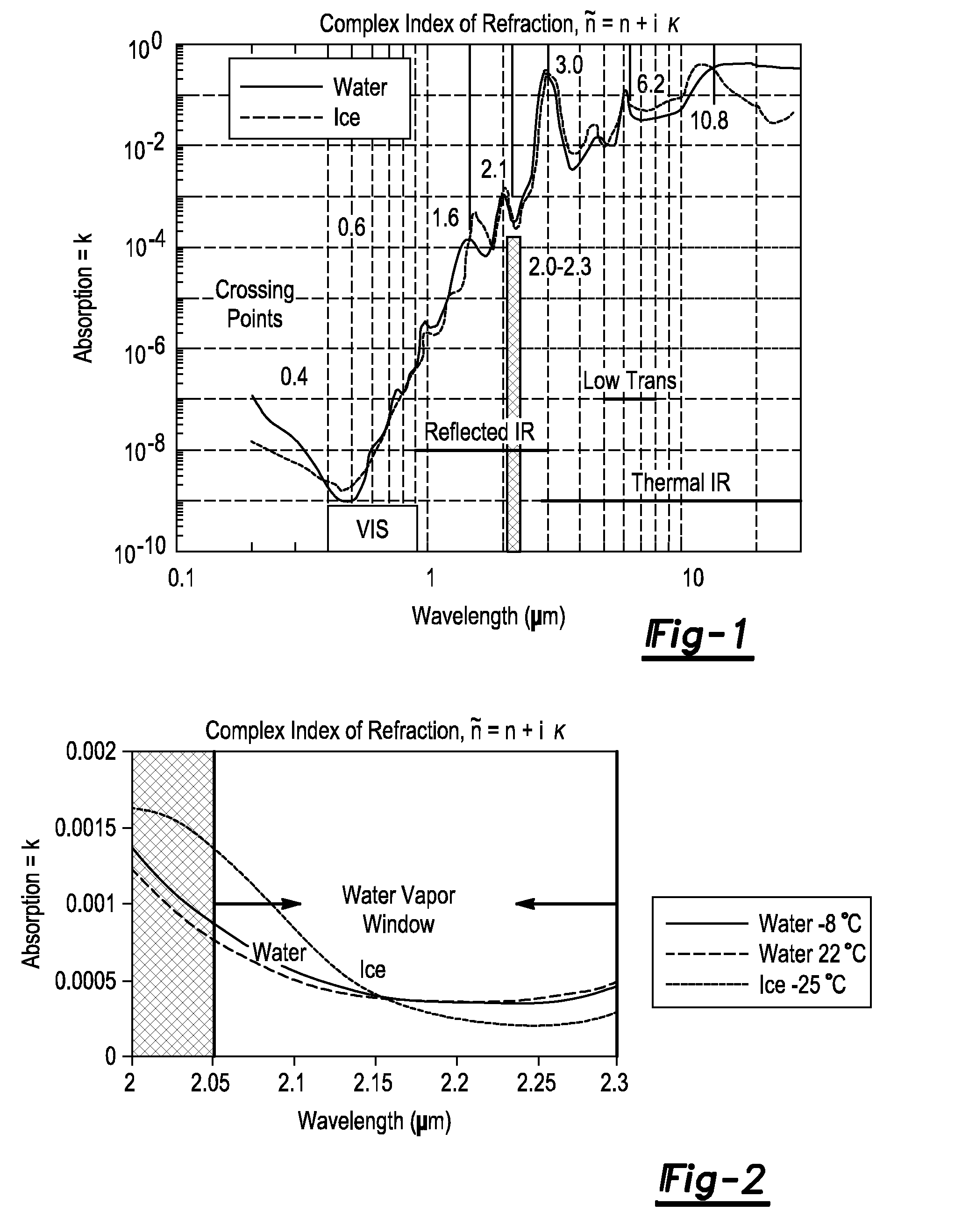
A system for detecting ice or water within an area of interest having a detection system measuring radiance or reflectance of the area of interest when exposed to shortwave infrared radiation having a wavelength in the range containing a crossover point between the curves representing the absorption of electromagnetic radiation by ice and water. The detection system measures the radiance or reflectance in a first band having a wavelength in a spectral band on a first side of the crossover point and outputting a first band signal, and further measures the radiance or reflectance in a second band having a wavelength in a spectral band on a second opposing side of the same crossover point and outputting a second band signal. A processing unit determines a ratio of the first band signal and the second band signal and compares the ratio to a predetermined critical ratio and outputs a determination signal indicating presence of ice or water.

Description

CROSS-REFERENCE TO RELATED APPLICATIONS[0001]This application is a continuation-in-part Application of U.S. patent application Ser. No. 14 / 277,082 filed on May 14, 2014 which claims the benefit of U.S. Provisional Application No. 61 / 895,040, filed on Oct. 24, 2013. The entire disclosures of each of the above applications are incorporated herein by reference.FIELD[0002]The present disclosure relates to an optical system capable of detecting ice and water on a wide variety of surfaces, such as bridges, roads, sidewalks, railways, runaways, for use with ground-based vehicles and further capable of detecting supercooled water droplets that freeze when impacting the surfaces of airborne vehicles, such as aircrafts, Unmanned Air Vehicles (UAVs) and other objects of interest.BACKGROUND AND SUMMARY[0003]This section provides background information related to the present disclosure that is not necessarily prior art. This section further provides a general summary of the disclosure, and is no...

Claims


Application Information

Patent Timeline
IPC IPC(8): G01N21/55B64C19/00B60T7/12G01N21/59
CPCG01N21/55B60T7/12B64C19/00G01N21/59B64D15/20G01N21/3554G01N2021/3513G01N2021/392
Inventor RENNO, NILTON O.
Owner RGT UNIV OF MICHIGAN
Why Eureka
Try Eureka