Display panel

a display panel and display technology, applied in static indicating devices, instruments, non-linear optics, etc., can solve the problems of poor luminous efficiency, high power consumption, and display problems that have gradually become history, and achieve high luminous efficiency and power saving

Active Publication Date: 2015-05-07
AU OPTRONICS CORP
View PDF3 Cites 26 Cited by
  • Summary
  • Abstract
  • Description
  • Claims
  • Application Information

AI Technical Summary

Benefits of technology

[0008]Accordingly, since the display provided in the invention has the first and the second white filter patterns including different white light CIE color coordinates and five types of

Problems solved by technology

As the technology advances, bulky Cathode Ray Tube (CRT) displays have gradually become history.
Since the white light OLED has poor luminous efficiency and yields difficulty to comply with the perfect white poi

Method used


Image

  • Display panel
  • Display panel
  • Display panel

Examples


first embodiment

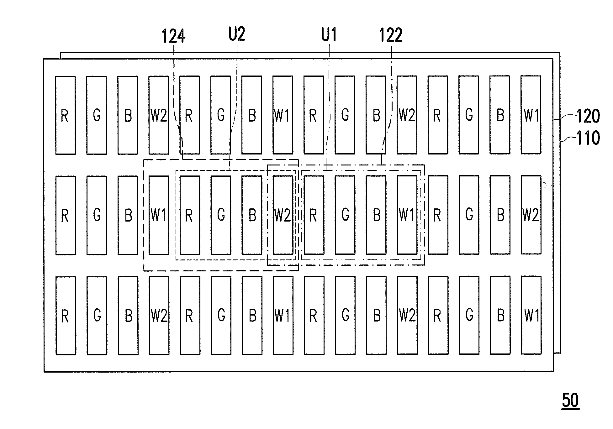
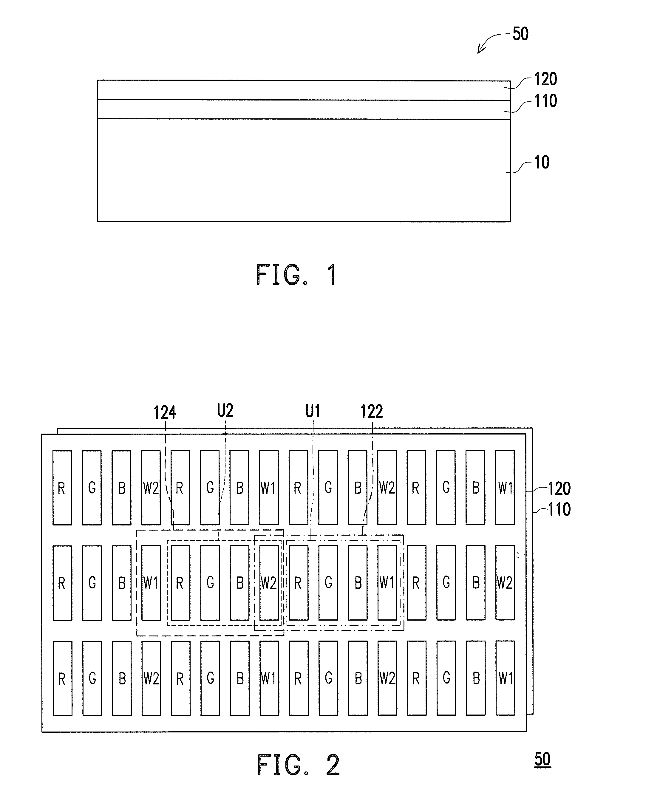
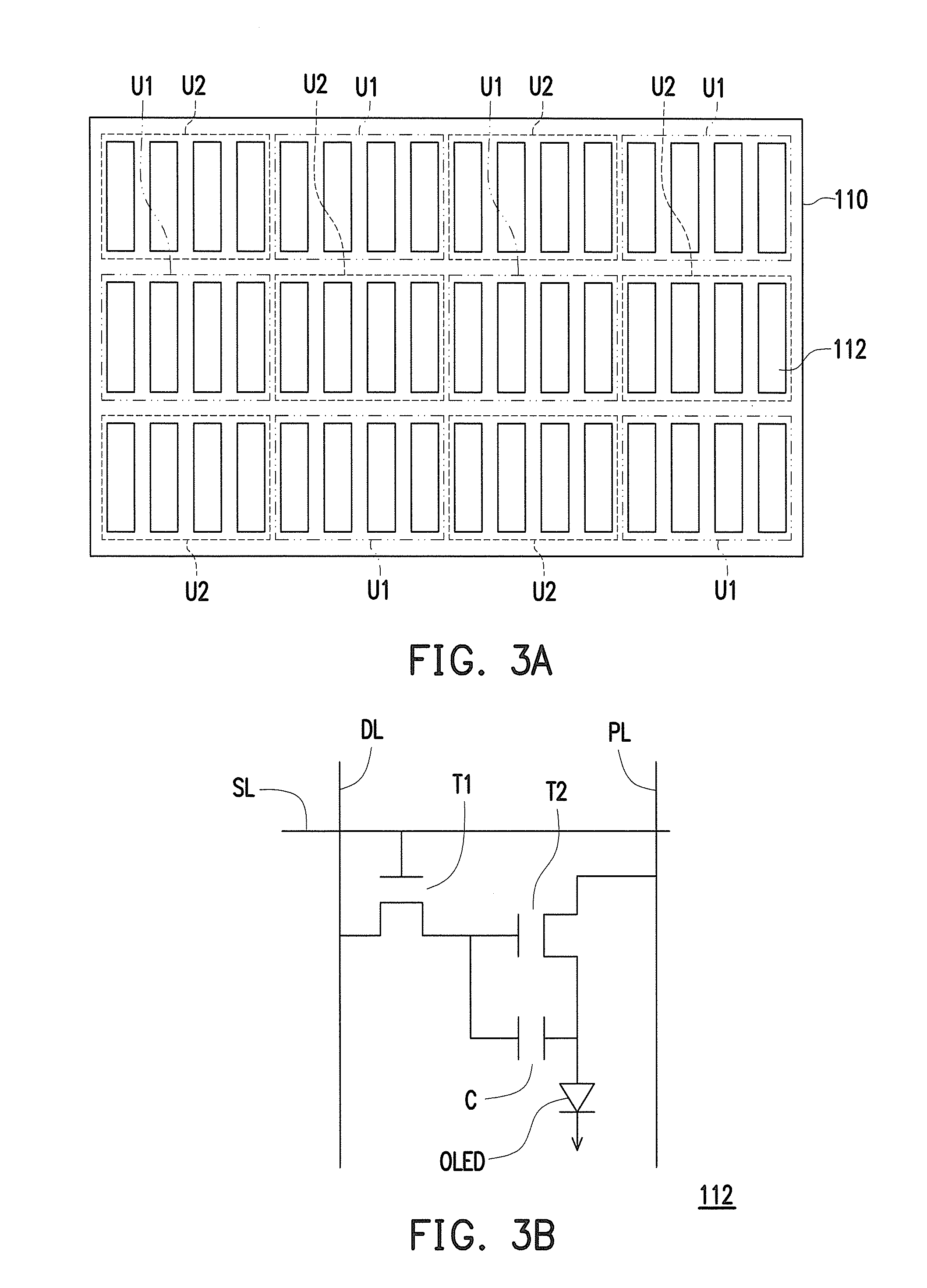
[0021]FIG. 1 is a schematic cross-sectional view of a display panel according to an embodiment of the invention and FIG. 2 is a schematic top view of the display panel shown in FIG. 1. FIG. 3A and FIG. 3B are respectively a schematic top view of a pixel array and an equivalent circuit diagram of a light emitting unit in the pixel array layer of the invention.

[0022]Please refer to FIG. 1, FIG. 2, FIG. 3A, and FIG. 3B simultaneously, the display panel 50 is, for example, a self-illuminating display panel. In the present embodiment, an OLED display panel (namely, Organic Electro-luminescence Display panel, OELD panel) is used as an example of the display panel 50 for demonstration. The display panel 50 includes a substrate 10, a pixel array layer 110, and a color filter layer 120.

[0023]The material of the substrate 10 includes glass, quartz, organic polymer, metal, or the like.

[0024]The pixel array layer 110 is located on the substrate 10, and the pixel array layer 110 includes a plur...

second embodiment

[0048]In the aforementioned embodiments according to FIG. 2 through FIG. 3B, the plurality of filter patterns of the color filter layer 120 are arranged in the form of strip with single row and multiple columns as an example for demonstration. However, it construes no limitation in the invention. In other embodiment of the invention (for example, as shown in second embodiment according to FIG. 11 through FIG. 12B), the plurality of filter patterns of the color filter layer 120 can also arranged in the form of delta, mosaic, or other suitable arrangements.

[0049]FIG. 11 is a schematic top view of a display panel according to second embodiment of the invention. FIG. 12A and FIG. 12B are respectively a schematic top view of a pixel array and an equivalent circuit diagram of a light emitting unit (namely, the white organic light emitting unit 212) in the pixel array layer according to second embodiment of the invention. The embodiment corresponding to FIG. 11 through FIG. 12B is similar ...


PUM


Abstract

A display panel has first and second unit regions staggered to each other and includes a pixel array layer and a color filter layer. The pixel array layer includes white organic light emitting units generating a white light. The color filter layer includes red, green and blue filter patterns and first and second white filter patterns. A first white light CIE color coordinate of the white light passing through the first white filter patterns is different from a second white light CIE color coordinate of the white light passing through the second white filter patterns. Each first unit region has one red filter pattern, one green filter pattern, one blue filter pattern, and one first white filter pattern disposed therein, and each second unit region has one red filter pattern, one green filter pattern, one blue filter pattern, and one second white filter pattern disposed therein.

Description

CROSS-REFERENCE TO RELATED APPLICATION[0001]This application claims the priority benefit of Taiwan application serial no. 102139738, filed on Nov. 1, 2013. The entirety of the above-mentioned patent application is hereby incorporated by reference herein and made a part of this specification.BACKGROUND OF THE INVENTION[0002]1. Technical Field[0003]The invention generally relates to a display panel, and more particularly to a color filter layer of the display panel.[0004]2. Description of Related Art[0005]As the technology advances, bulky Cathode Ray Tube (CRT) displays have gradually become history. Therefore, displays such as Liquid Crystal Display (LCD), Organic Light Emitting Diode display (OLED display), Electro-Phoretic Display (EPD), and Plasma Display Panel (PDP) have gradually become the mainstream for future displays. The structure using white light OLED as a light source along with a color filter layer containing three primary colors RGB is one of the full-color technologie...

Claims


Application Information

Patent Timeline
IPC IPC(8): H01L27/32
CPCH01L27/322G09G3/2003G09G3/3225G09G3/3607G09G2300/0452H10K59/351H10K59/38G09G5/02G02F1/133514G09G3/3611H10K50/852
Inventor XI, PENG-BOHSU, YA-LING
Owner AU OPTRONICS CORP
Why Eureka
Try Eureka