Negative electrode for power storage device, power storage device, and electrical device

a technology of power storage device and negative electrode, which is applied in the direction of non-aqueous electrolyte accumulator electrode, cell components, electrical apparatus, etc., can solve the problems of promoting the deterioration of the power storage device, and achieve excellent cycle characteristics, high charge and discharge efficiency, and high capacitance

Inactive Publication Date: 2015-05-14
SEMICON ENERGY LAB CO LTD
View PDF8 Cites 6 Cited by
  • Summary
  • Abstract
  • Description
  • Claims
  • Application Information

AI Technical Summary

Benefits of technology

[0011]An object of one embodiment of the present invention is to provide a power storage device having high capacitance. Another object of one embodiment of the present invention is to provide a power storage device with excellent cycle characteristics. Another object of one embodiment of the present invention is to provide a power storage device with high charge and discharge efficiency. Another object of one embodiment of the present invention is to provide a power storage device including a negative electrode with low resistance. Another object of one embodiment of the present invention is to provide a novel power storage device or the like.

Problems solved by technology

In this case, the power storage device is bent with the flexible portion, so that repeated change in the form of the power storage device might cause separation between a current collector and an active material in the power storage device.
As a result, deterioration of the power storage device might be promoted.

Method used


Image

  • Negative electrode for power storage device, power storage device, and electrical device
  • Negative electrode for power storage device, power storage device, and electrical device
  • Negative electrode for power storage device, power storage device, and electrical device

Examples


embodiment 1

[0046]In this embodiment, a negative electrode and an electrolyte and solvent of an electrolytic solution that are used in a power storage device of one embodiment of the present invention will be described. In addition, a method for fabricating a negative electrode will be described.

[Negative Electrode Structure 1]

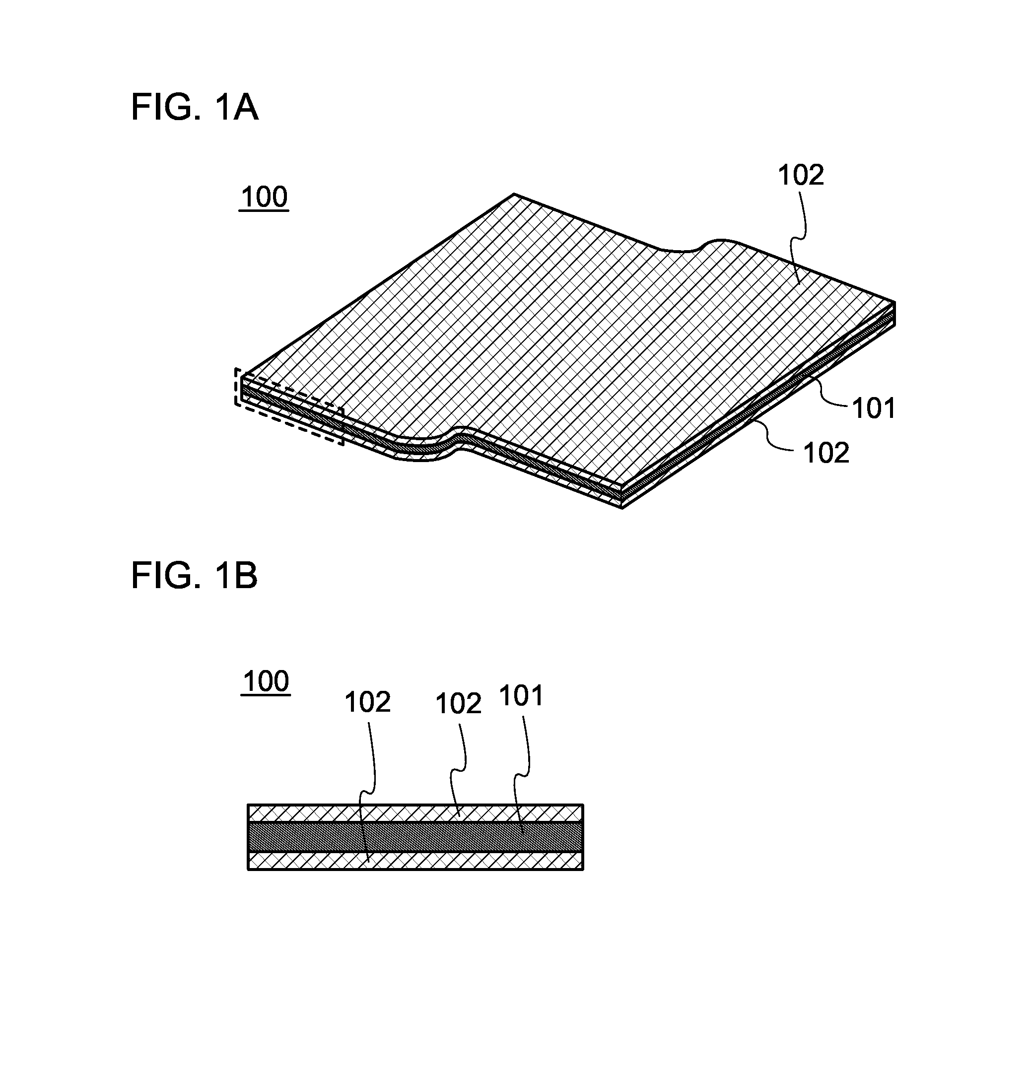
[0047]FIG. 1A is an overhead view of a negative electrode, and FIG. 1B is a cross-sectional view of a portion surrounded by a broken line in FIG. 1A. A negative electrode 100 has a structure in which a negative electrode active material layer 102 is provided over a negative electrode current collector 101. Although the negative electrode active material layers 102 are provided so that the negative electrode current collector 101 is sandwiched therebetween in FIGS. 1A and 1B, the negative electrode active material layer 102 may be formed over only one surface of the negative electrode current collector 101. The negative electrode active material layer 102 includes a negati...

embodiment 2

[0112]In this embodiment, the structure of a power storage device including the negative electrode fabricated by the fabricating method described in Embodiment 1 will be described with reference to FIGS. 11A to 11C, FIGS. 12A and 12B, FIG. 13, and FIGS. 14A and 14B. Structural examples of power storage devices (storage batteries) will be described with reference to FIGS. 15A and 15B, FIGS. 16A and 16B, FIGS. 17A to 17C, FIGS. 18A to 18C, and FIGS. 19A and 19B. Examples of electrical devices will be described with reference to FIGS. 20A1 to 20B2.

[Coin-type Storage Battery]

[0113]FIG. 11A is an external view of a coin-type (single-layer flat type) storage battery, and FIG. 11B is a cross-sectional view thereof.

[0114]In a coin-type storage battery 300, a positive electrode can 301 doubling as a positive electrode terminal and a negative electrode can 302 doubling as a negative electrode terminal are insulated from each other and sealed by a gasket 303 made of polypropylene or the like. ...

example 1

[0185]In this example, half cells were fabricated using the negative electrode described in Embodiment 1 and measurement of the half cells was performed.

(Grinding of Silicon)

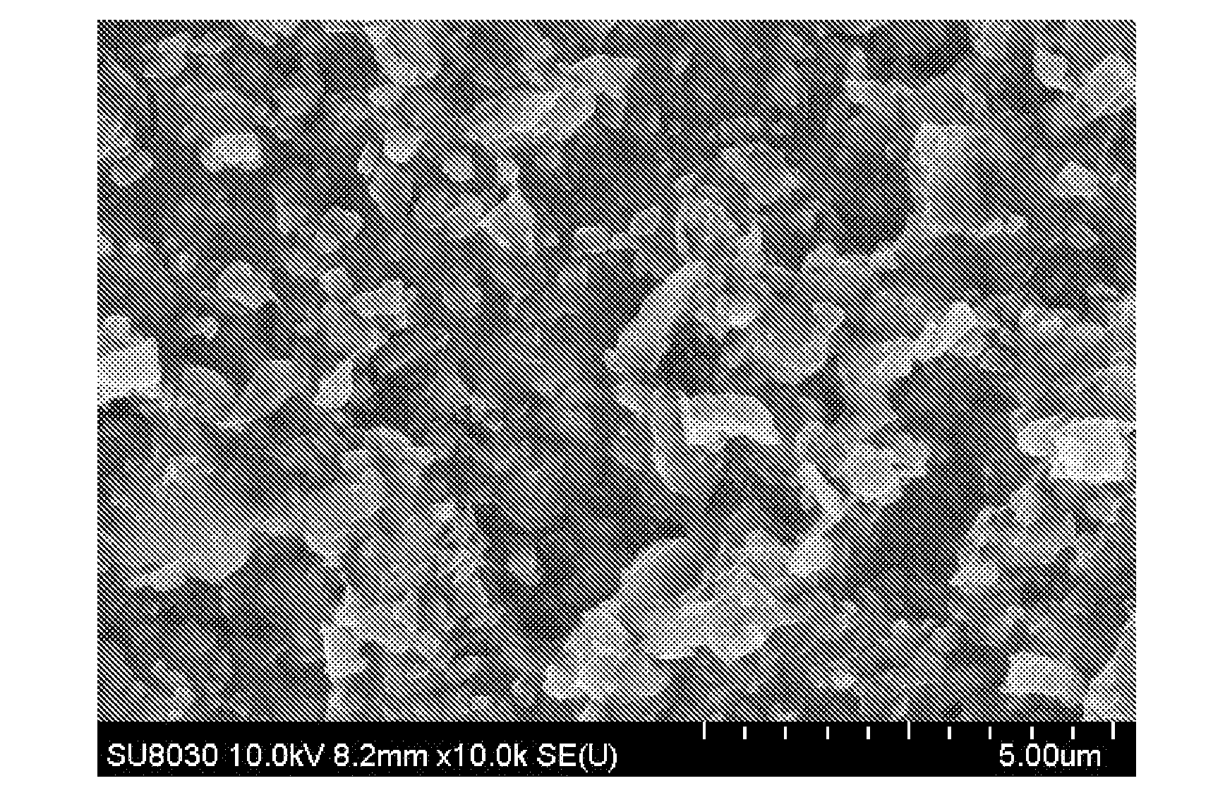
[0186]Silicon wafers were ground. Table 1 shows samples of the ground silicon as Samples A to H and Comparative Sample I. The silicon wafers used had n-type conductivity / p-type conductivity and resistivities shown in Table 1. The plane directions of the silicon wafers in Table 1 are all the (100) plane. First, each of the silicon wafers was cut into 6-cm squares and ground in a mortar. After that, grinding was further performed in a ball mill with a ball diameter of 3 mm under the conditions of RPM and treatment time that are shown in Table 1. Balls and the silicon ground in a mortar were put in a 54-ml ball mill. The weight of the balls is 22 g, and the weights of silicon are as follows: Samples A, E, H: 2 g; Samples B, C, D, F, G: 4 g; and Comparative Sample I: 8 g. Acetone was used as a solvent. The size of t...


PUM

PropertyMeasurementUnit
sizeaaaaaaaaaa
resistivityaaaaaaaaaa
sizeaaaaaaaaaa

Abstract

A power storage device having high capacitance is provided. A power storage device with excellent cycle characteristics is provided. A power storage device with high charge and discharge efficiency is provided. A power storage device including a negative electrode with low resistance is provided. A negative electrode for the power storage device includes a current collector and an active material layer including a plurality of active material particles over the current collector. The active material particle is silicon, and the size of the silicon particle is greater than or equal to 0.001 μm and less than or equal to 7 μm.

Description

BACKGROUND OF THE INVENTION[0001]1. Field of the Invention[0002]The present invention relates to an object, a method, or a manufacturing method. The present invention relates to a process, a machine, manufacture, or a composition of matter. One embodiment of the present invention relates to a semiconductor device, a display device, a light-emitting device, a power storage device, a driving method thereof, or a manufacturing method thereof. One embodiment of the present invention relates to a positive electrode active material, a secondary battery, and a manufacturing method thereof. In particular, one embodiment of the present invention relates to an electrode for a power storage device and a manufacturing method thereof.[0003]2. Description of the Related Art[0004]In recent years, portable electronic devices such as mobile phones, smartphones, electronic book (e-book) readers, and portable game machines have been widely used. Being used as power sources for driving these devices, p...

Claims


Application Information

Patent Timeline
Patent Type & Authority Applications(United States)
IPC IPC(8): H01M4/38H01M4/62
CPCH01M4/386H01M4/625H01M2004/021H01M4/134H01M4/38Y02E60/10
Inventor OGINO, KIYOFUMIYONEDA, YUMIKOYATABE, RIKAINOUE, NOBUHIRO
Owner SEMICON ENERGY LAB CO LTD
Why Eureka
Try Eureka