Methods and systems for manufacturing components from articles formed by additive-manufacturing processes

a technology of additive manufacturing and manufacturing components, applied in the direction of manufacturing tools, machines/engines, turbines, etc., can solve the problems of low yield, long lead-time, high cost of conventional methods, etc., and achieve good electrical continuity and improve the surface finish of internal and external surfaces.

Active Publication Date: 2015-05-28
HONEYWELL INT INC
View PDF13 Cites 53 Cited by
  • Summary
  • Abstract
  • Description
  • Claims
  • Application Information

AI Technical Summary

Benefits of technology

[0050]In this manner, an internally micro-machine component is fabricated. The micro-machining process removes the surface roughness 505 from within the internal passages of the component 500. The cathode remains entirely outside of the component at all times, which allows for small, complex configurations of internal surfaces (cooling channels, etc.) to be suitably micro-machined using the presently described embodiments.
[0051]In an alternate embodiment, a progressive electrolytic resistive layer process is disclosed that utilizes a special form of anodic electrochemical micro-machining having a beneficial precipitate layer to improve the surface finish of internal and external surfaces. This process does not require the flowing of an electrolyte solution; rather, the component is placed in a fluid reservoir, such as reservoir 701 or 710. The process is performed, as will be described below, to avoid harming the external features of the component 500, while still allowing for the micro-machining of the internal passages of the component 500, even though the entire component 500 is placed in the reservoir. The power supply 704 operates as described above, but the pump 706, control valve 707, flow meter 708, separator 712, and filter 714 need not be operating during the micro-machin...

Problems solved by technology

Components with relatively complex three-dimensional (3D) geometries raise difficult fabrication issues.
Such conventional methods are not only expensive and have long lead-times, but may additionally have low yields.
Development time and cost for certain components may also be magnified because such components generally require several iterations, including iterations as a result of intentional design decisions.
Cracks may develop at these interfaces or cut through or across deposit layers dues to stresses inherent with the additive manufacturing process and/or the metallurgy of the build material.
However, for components with significant surface roughness, the encapsulation process may not sufficiently bridge and cover the surface-connected defects.
Surface roughness may also be objectionable to customer perception of quality and may interfere with the functionality of the component.
For example, excessive surface roughness may restrict or impede airflow, collect debris, act as a stress riser, and otherwise detract from the component design.
Unfortunat...

Method used


Image

  • Methods and systems for manufacturing components from articles formed by additive-manufacturing processes
  • Methods and systems for manufacturing components from articles formed by additive-manufacturing processes
  • Methods and systems for manufacturing components from articles formed by additive-manufacturing processes

Examples


Embodiment Construction

[0023]The following detailed description is merely exemplary in nature and is not intended to limit the invention or the application and uses of the invention. As used herein, the word “exemplary” means “serving as an example, instance, or illustration.” Thus, any embodiment described herein as “exemplary” is not necessarily to be construed as preferred or advantageous over other embodiments. All of the embodiments described herein are exemplary embodiments provided to enable persons skilled in the art to make or use the invention and not to limit the scope of the invention which is defined by the claims. Furthermore, there is no intention to be bound by any expressed or implied theory presented in the preceding technical field, background, brief summary, or the following detailed description.

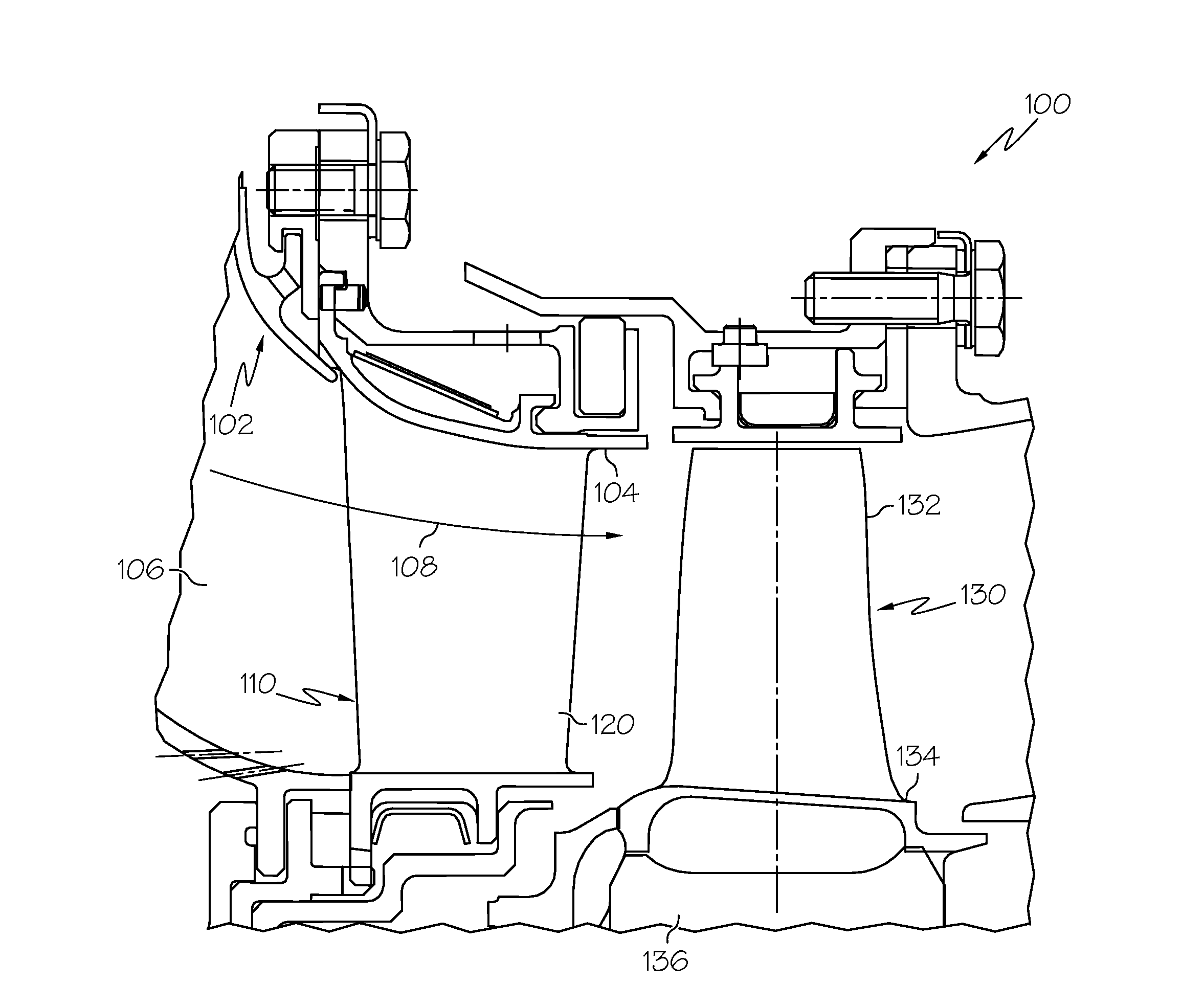
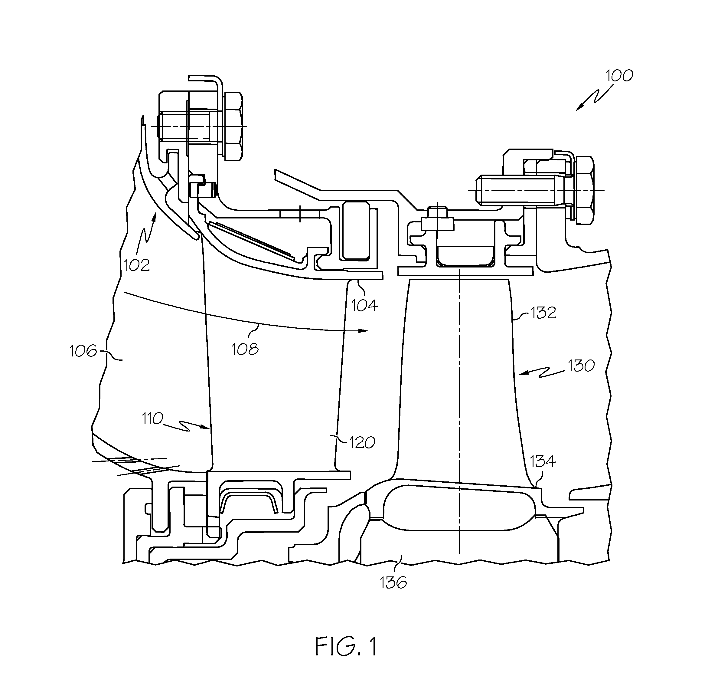
[0024]Various embodiments are directed to methods for manufacturing components from components formed by an additive manufacturing process such as electron beam melting or direct metal laser fu...


PUM

PropertyMeasurementUnit
Solutionaaaaaaaaaa

Abstract

A method is provided for manufacturing a component. The method includes connecting a component comprising an internal passage and formed by an additive manufacturing process to a power supply, the component functioning as an anode, connecting a cathode to the power supply, the cathode being disposed in an electrolyte solution, the cathode being positioned externally to the internal passage of the component, contacting the internal passage of the component with the electrolyte solution, and using the power supply, applying a potential difference and current flow between the component and the cathode.

Description

TECHNICAL FIELD[0001]The present invention generally relates to surface improvement methods for manufacturing metallic or electrically conductive components, and more particularly relates to methods for manufacturing components from articles formed by additive-manufacturing processes.BACKGROUND[0002]Components with relatively complex three-dimensional (3D) geometries raise difficult fabrication issues. Conventional fabrication techniques include forging, casting, and / or machining. Such conventional methods are not only expensive and have long lead-times, but may additionally have low yields. Development time and cost for certain components may also be magnified because such components generally require several iterations, including iterations as a result of intentional design decisions.[0003]Additive manufacturing (AM) processes (including those which form “cores” for subsequent conventional casting) have been developed to fabricate components having relatively complex three dimensi...

Claims


Application Information

Patent Timeline
IPC IPC(8): C25D3/44C25D7/00
CPCC25D7/00C25D3/44F01D5/186F01D5/187F01D5/288F05D2230/31B22F5/10B22F2999/00B23H3/00C25F3/26C25F7/00B23H9/10B22F2003/247B33Y10/00B23H9/16B22F5/04Y02P10/25B22F10/62B22F10/64B22F10/20
Inventor MORRIS, MARK C.SCHWARZ, KLAUS HELMUTGODFREY, DONALD G.SZUROMI, ANDY
Owner HONEYWELL INT INC
Why Eureka
Try Eureka