
Synthesis Method of Organometallic Complex, Synthesis Method of Pyrazine Derivative, 5,6-Diaryl-2-Pyrazyl Triflate, Light-Emitting Element, Light-Emitting Device, Electronic Device, and Lighting Device

a technology of organometallic complexes and synthesis methods, which is applied in the direction of cadmium organic compounds, group 3/13 element organic compounds, and group 5/15 element organic compounds, etc., can solve the problems that the purification process of organic compounds cannot be easily removed by sublimation, and it is difficult to make an end product impurity-free. , to achieve the effect of reducing impurities, high reliability and high reliability

Active Publication Date: 2015-05-28
SEMICON ENERGY LAB CO LTD
View PDF37 Cites 5 Cited by
  • Summary
  • Abstract
  • Description
  • Claims
  • Application Information

AI Technical Summary

Benefits of technology

This patent describes a new method for efficiently synthesizing organometallic complexes with reduced halogen content. This method uses a novel organic compound called 5,6-diaryl-2-pyrazyl triflate, which is formed using a specific process. This method reduces impurities and allows for the production of highly reliable light-emitting elements, devices, and lighting devices. The technical effects of this patent include high-yield synthesis of organometallic complexes using inexpensive materials and reduced halogen content. Additionally, the formation of highly reliable light-emitting devices and lighting devices using the synthesized organometallic complexes as an EL material is also possible.

Problems solved by technology

However, purification by sublimation cannot necessarily remove impurities easily in synthesis of organic compounds.
When a material used in a synthesis process contains a substance which potentially acts as an impurity, it is sometimes technically difficult to make an end product impurity-free.

Method used


Image

  • Synthesis Method of Organometallic Complex, Synthesis Method of Pyrazine Derivative, 5,6-Diaryl-2-Pyrazyl Triflate, Light-Emitting Element, Light-Emitting Device, Electronic Device, and Lighting Device
  • Synthesis Method of Organometallic Complex, Synthesis Method of Pyrazine Derivative, 5,6-Diaryl-2-Pyrazyl Triflate, Light-Emitting Element, Light-Emitting Device, Electronic Device, and Lighting Device
  • Synthesis Method of Organometallic Complex, Synthesis Method of Pyrazine Derivative, 5,6-Diaryl-2-Pyrazyl Triflate, Light-Emitting Element, Light-Emitting Device, Electronic Device, and Lighting Device

Examples


embodiment 1

[0042]In this embodiment, a method for synthesizing an organometallic complex that is one embodiment of the present invention is described. Hereinafter, the explanation is mainly given to a synthetic method of an organoiridium complex. However, the embodiment is not limited to the synthetic method of an organoiridium complex but includes those of an organoplatinum complex, an organorhodium complex, and the like.

[0043]One embodiment of the present invention is a synthesis method that includes a synthetic pathway to a novel 5,6-diaryl-2-pyrazyl triflate, which is a synthetic intermediate, thereby producing an organometallic complex with reduced chlorine content in a high yield.

>

[0044]First, a synthesis method of 5,6-diaryl-2-pyrazyl triflate represented by General Formula (G0) is described.

[0045]The novel 5,6-diaryl-2-pyrazyl triflate (General Formula (G0)) is synthesized in the following manner. As shown in Synthesis Scheme (A-1) below, a 1,2-diaryl diketone (General Formula (a1)) an...

embodiment 2

[0064]In this embodiment, a light-emitting element in which the organometallic complex obtained by the synthesis method of one embodiment of the present invention is used as an EL material is described with reference to FIG. 1.

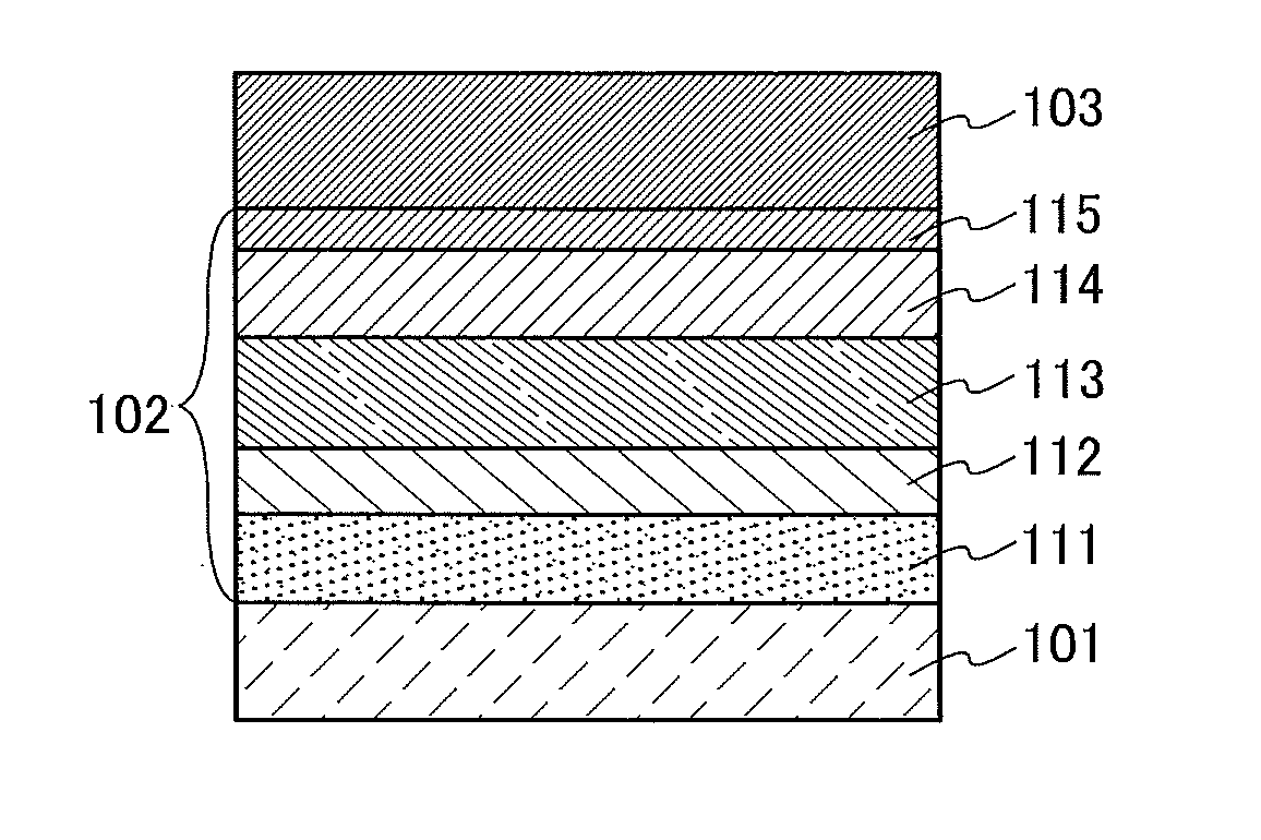
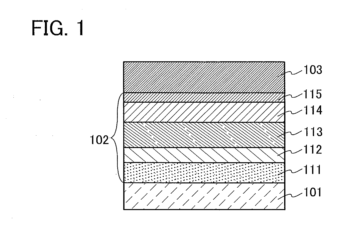
[0065]In a light-emitting element described in this embodiment, as illustrated in FIG. 1, an EL layer 102 including a light-emitting layer 113 is interposed between a pair of electrodes (a first electrode (anode) 101 and a second electrode (cathode) 103), and the EL layer 102 includes a hole-injection layer 111, a hole-transport layer 112, an electron-transport layer 114, an electron-injection layer 115, and the like in addition to the light-emitting layer 113.

[0066]When voltage is applied to such a light-emitting element, holes injected from the first electrode 101 side and electrons injected from the second electrode 103 side recombine in the light-emitting layer 113 to lead a light-emitting substance contained in the light-emitting layer 113 to an excited s...

embodiment 3

[0092]Described in this embodiment is a case of fabricating a light-emitting element (hereinafter, a tandem light-emitting element) that has a structure in which a charge-generation layer is provided between a plurality of EL layers and the organometallic complex obtained by the synthesis method of one embodiment of the present invention is used as an EL material in the EL layers.

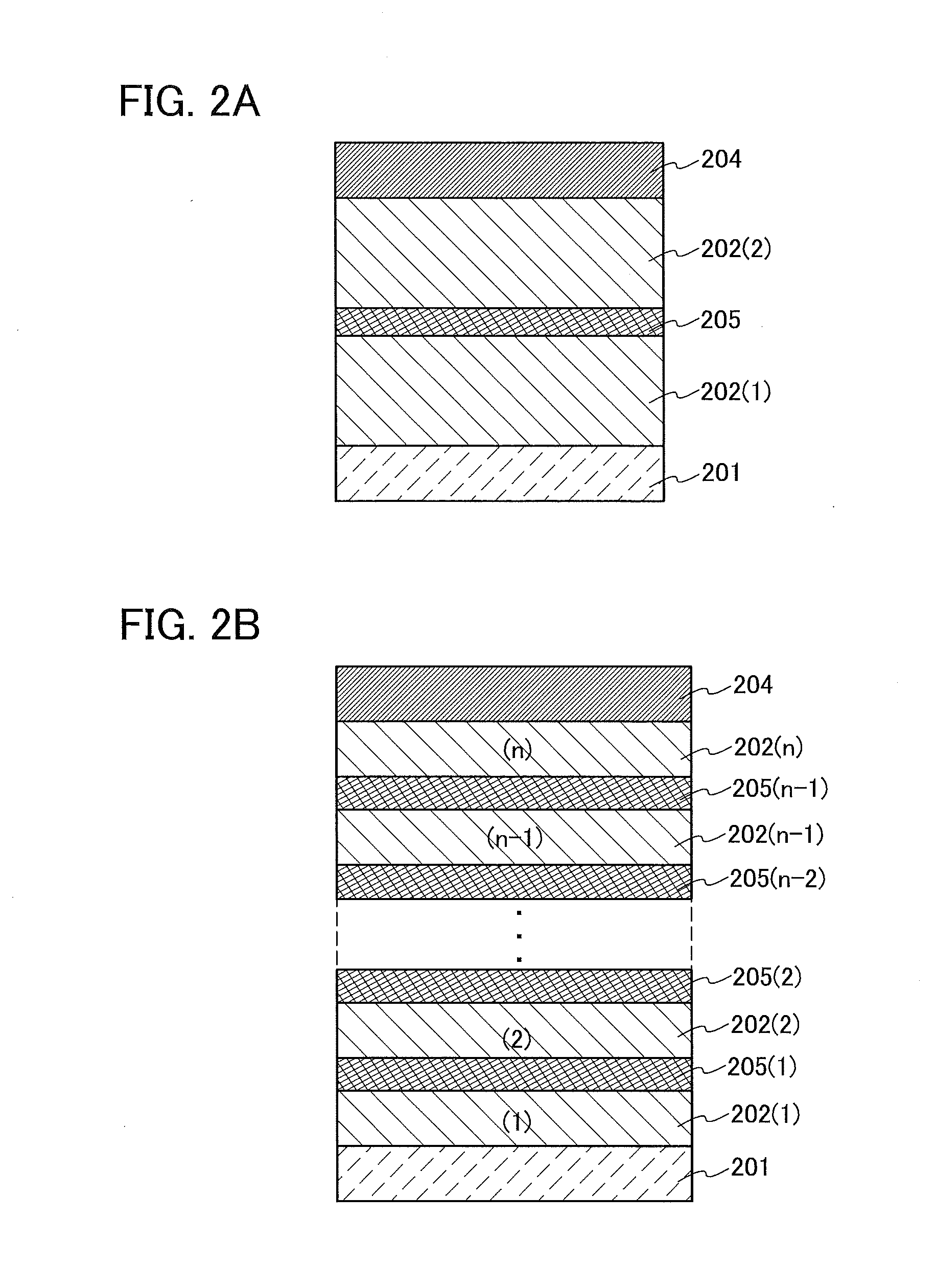
[0093]A light-emitting element described in this embodiment is a tandem light-emitting element including a plurality of EL layers (a first EL layer 202(1) and a second EL layer 202(2)) between a pair of electrodes (a first electrode 201 and a second electrode 204) as illustrated in FIG. 2A.

[0094]In this embodiment, the first electrode 201 functions as an anode, and the second electrode 204 functions as a cathode. Note that the first electrode 201 and the second electrode 204 can have structures similar to those described in Embodiment 2. In addition, all or any of the plurality of EL layers (the first EL la...


PUM

PropertyMeasurementUnit
visible light transmittanceaaaaaaaaaa
energy gapaaaaaaaaaa

Abstract

Provided is a 5,6-diaryl-2-pyrazyl triflate, its synthetic method, and a method for synthesizing an organometallic complex having a triarylpyrazine ligand from the 5,6-diaryl-2-pyrazyl triflate. The triflate is readily obtained from the corresponding 5,6-diarylpyrazin-2-ol, and the palladium-catalyzed coupling of the 5,6-diaryl-2-pyrazyl triflate with an arylboronic acid derivative leads to a high yield of a triarylpyrazine derivative having high purity. The use of the triarylpyrazine derivative in the reaction with a metal compound such as a metal chloride results in an ortho-metallated organometallic complex with high purity. The high purity of the organometallic complex contributes to the extremely high durability of a light-emitting element.

Description

BACKGROUND OF THE INVENTION[0001]1. Field of the Invention[0002]One embodiment of the present invention relates to a novel method for synthesizing an organometallic complex such as an organoiridium complex. Another embodiment of the present invention relates to a novel method for synthesizing a triarylpyrazine derivative. Another embodiment of the present invention relates to 5,6-diaryl-2-pyrazyl triflate used for the above synthesis methods. Another embodiment of the present invention relates to a light-emitting element, a light-emitting device, an electronic device, and a lighting device each including an organometallic complex synthesized by the above synthesis method.[0003]Note that one embodiment of the present invention is not limited to the above technical field. Specifically, examples of the technical field of one embodiment of the present invention disclosed in this specification include a semiconductor device, a display device, a liquid crystal display device, a light-emit...

Claims


Application Information

Patent Timeline
Patent Type & Authority Applications(United States)
IPC IPC(8): H01L51/00C07D241/12H01L51/56C07F15/00H10K99/00
CPCH01L51/0085H01L51/56C07D241/12C07F15/0033C07D241/18C09K11/06C09K2211/185H10K85/342H10K50/11H10K2101/10H10K2102/103
Inventor INOUE, HIDEKOKUBOTA, TOMOHIROKANAMOTO, MIKI
Owner SEMICON ENERGY LAB CO LTD
Learn More