Dc-dc converter circuit using an llc circuit in the region of voltage gain above unity

a dc-dc converter and voltage gain technology, applied in the direction of efficient power electronics conversion, electric variable regulation, instruments, etc., can solve the problems of loss of efficiency, lack of galvanic isolation, and less than optimal efficiency of resonant circuits, so as to improve the controllability of dc-dc converters and minimize the effective voltage gain of resonant circuits

Inactive Publication Date: 2015-06-11
ARDA POWER
View PDF6 Cites 28 Cited by
  • Summary
  • Abstract
  • Description
  • Claims
  • Application Information

AI Technical Summary

Benefits of technology

[0041]In a still other aspect of the invention, a DC-DC converter if provided wherein the components are selected so as to minimize the e...

Problems solved by technology

While both of these circuits are capable of achieving very high conversion efficiency when the input-to-output voltage ratio is near unity and the switching frequency is relatively low, their efficiency Is less than optimal when the voltage ratio becomes high or the switching frequency is increased to reduce the total size of the converter.
In addition, in their basic form they do not provide galvanic isolation.
Loss of efficiency, along with other operational problem, are caused by circuit parasitics, including such circuit effects as diode forward voltage drop, switch and diode conduction losses, switching losses, switch capacitances, inductor winding capacitance, and lead and trace inductances.
Furthermore, it is known in the prior art that boost converters in particular are susceptible to parasitic effects and high efficiency operation requires low step up ration, e.g. 1:2 or 1:3.
Perfect matching is not viable in many applications.
This is undesirable as the inductor is typically the single most expensive component in the power circuit.
This is often not available.
20 kHz-100 kHz) such devices are not readily available thus they need to be created out of a series combination of an insulated-gate bipolar transistor (“IGBT”) and a diode, or a metal oxide semiconductor field effect transistor (“MOSFET”) MOSFET and a diode....

Method used


Image

  • Dc-dc converter circuit using an llc circuit in the region of voltage gain above unity
  • Dc-dc converter circuit using an llc circuit in the region of voltage gain above unity
  • Dc-dc converter circuit using an llc circuit in the region of voltage gain above unity

Examples


Embodiment Construction

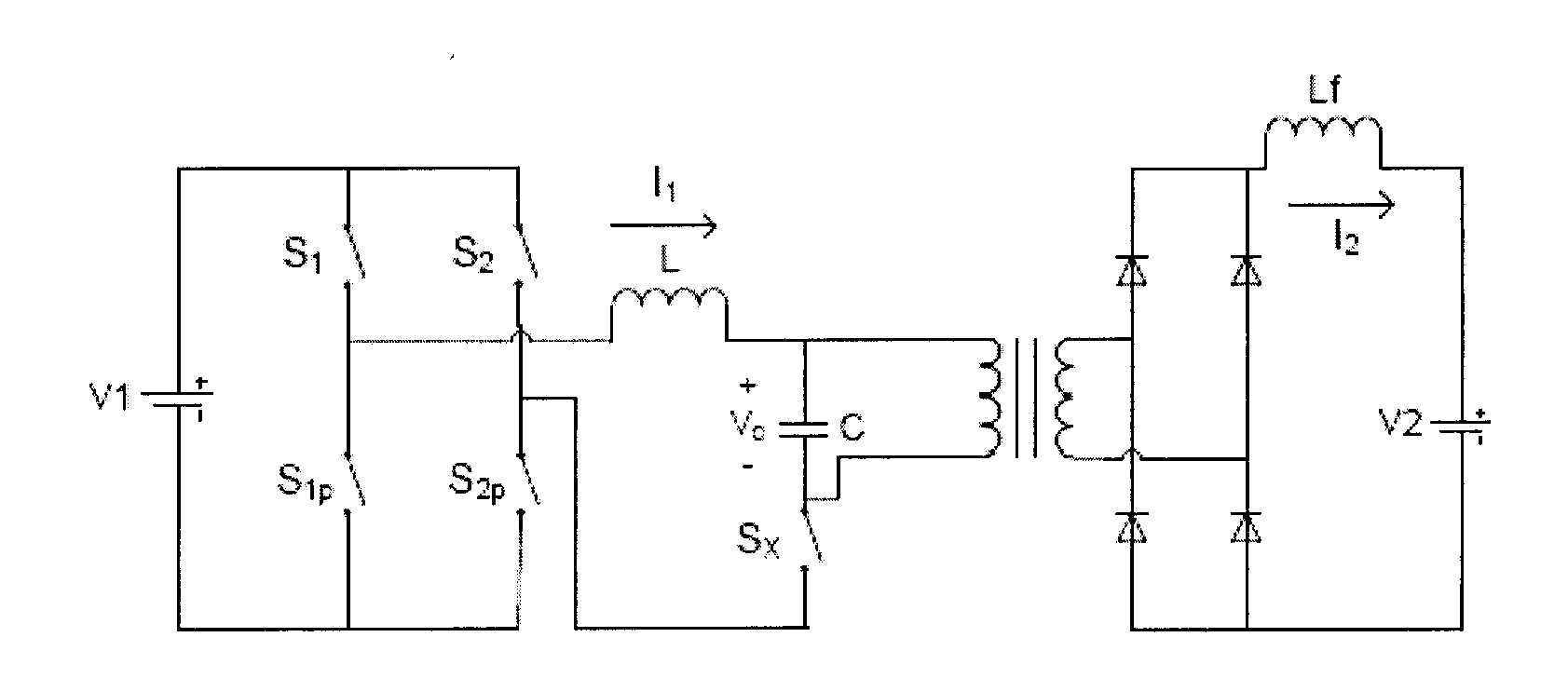
[0077]The present invention describes a number of innovations related to the subject matter of the Base Application. The present invention includes (A) a novel and innovative resonant DC-DC converter that employs a high boost resonant tank to enable power flow control between externally determined input and output voltages using frequency control, with or without use of an interrupt switch (the “Improved DC-DC Converter”), (B) a method of operating a resonant DC-DC converter to achieve high boost resonant tank operation, which is suitable for improving the performance of resonant converters based on different topologies (“method of operation”), including but not limited to the Improved DC-DC Converter; and (C) a method for designing DC-DC converters (having different topologies) for improved performance using the method of operation (“design method”). The design method includes identification of circuit design parameters that enable use of the method of operation. Performance improv...


PUM


Abstract

A method of operating a resonant DC-DC converter is provided where the resonant DC-DC converter includes a high voltage boost LLC circuit. The method includes providing variable power flow control to the LLC circuit with externally determined input and output voltages using frequency control. Frequency control is applied such that it emulates different loading conditions. For fixed input and output voltages this corresponds to operating along horizontal curves on the voltage gain compared to the switching frequency operating plane. A DC-DC converter is also provided including (A) a low voltage full-bridge or half-bridge DC-AC converter; (B) an LLC resonant tank; (C) a high voltage AC-DC converter or rectifier; and (D) a high voltage controllable switch; wherein the high voltage controllable switch is controllable to regulate power flow from an input to an output of the DC-DC converter based on an externally determined voltage gain ratio, wherein the LLC resonant lank operates with a minimum boosting having an effective value above unity over the entire operating range. A method of designing a resonant DC-DC converter for high voltage boost ratio is also provided.

Description

PRIORITY CLAIM[0001]This application claims priority to U.S. patent application Ser. No. 13 / 469,060 filed on May 10, 2012, which is hereby incorporated by reference in its entirety (the “Base Patent”).FIELD OF THE INVENTION[0002]This present invention relates generally to a power converting apparatus, and more specifically to a DC-DC converter using an LLC circuit in the region of voltage gain above unity.BACKGROUND TO THE INVENTION[0003]Direct current (DC) architectures are well known, for example for the transmission and distribution of power. DC architectures generally provide efficient (low loss) distribution of electrical power relative to alternating current (AC) architectures.[0004]The importance of DC architectures has increased because of factors including: (1) the reliance of computing and telecommunication equipment on DC input power, (2) the reliance of variable speed AC and DC drives on DC input power, (3) the production of DC power by solar photovoltaic systems, fuel c...

Claims


Application Information

Patent Timeline
IPC IPC(8): H02M3/335
CPCH02M3/33507H02M3/158Y02B70/10H02M1/0058H02M3/33573H02M3/33571H02M3/01
Inventor FROST, DAMIEN FRANCISZUBIETA, LUIS EDUARDOLEHN, PETER WALDEMAR
Owner ARDA POWER
Why Eureka
Try Eureka