Method and apparatus for measurement of neural response

a neural response and neural response technology, applied in the field of neural response measurement, can solve the problems of difficult task, significant obstacle to isolating the cap of interest, and poorly understood precise mechanisms involved, and achieve the effect of reducing the dynamic range requirements of implanted amplifiers, simple morphology, and low dynamic rang

Active Publication Date: 2015-06-18
SALUDA MEDICAL PTY LTD
View PDF2 Cites 55 Cited by
  • Summary
  • Abstract
  • Description
  • Claims
  • Application Information

AI Technical Summary

Benefits of technology

[0032]While recovering charge by short circuiting the stimulus electrodes together, it may in some embodiments be advantageous to disconnect the sense electrode from the measurement circuitry, for example by setting a sample-and-hold circuit to “hold”.
[0033]Embodiments of the invention may prove beneficial in obtaining a CAP measurement which has lower dynamic range and simpler morphology as compared to systems more susceptible to artefact. Such embodiments of the present invention may thus reduce the dynamic range requirements of implanted amplifiers, and may avoid or reduce the complexity of signal processing systems for feature extraction, simplifying and miniaturizing an implanted integrated circuit. Such embodiments may thus be particularly applicable for an automated implanted evoked response feedback system for stimulus control. Thus, in a further aspect, the present invention provides a method for feedback control of a neural stimulus, the method comprising an implanted control unit obtaining a CAP measurement in accordance with the method of the first aspect, and the implanted control unit using the obtained CAP measurement to control the delivery of subsequent neural stimuli by the implant.

Problems solved by technology

While the clinical effect of spinal cord stimulation (SCS) is well established, the precise mechanisms involved are poorly understood.
However, this can be a difficult task as an observed CAP signal will typically have a maximum amplitude in the range of microvolts, whereas a stimulus applied to evoke the CAP is typically several volts.
Electrode artefact usually results from the stimulus, and manifests as a decaying output of several millivolts throughout the time that the CAP occurs, presenting a significant obstacle to isolating the CAP of interest.
The capacitor recovers charge at the highest rate immediately after the stimulus, undesirably causing greatest artefact at the same time that the evoked response occurs.
To resolve a 10 uV SCP with 1 uV resolution in the presence of an input 5V stimulus, for example, requires an amplifier with a dynamic range of 134 dB, which is impractical in implant systems.
As the neural response can be contemporaneous with the stimulus and / or the stimulus artefact, CAP measurements present a difficult challenge of amplifier design.
In practice, many non-ideal aspects of a circuit lead to artefact, and as these mostly have a decaying exponential appearance that can be of positive or negative polarity, their identification and elimination can be laborious.
At typical neural conduction velocities, this requires that the measurement electrodes be spaced around 10 cm or more away from the stimulus site, which is undesirable as the measurement then necessarily occurs in a different spinal segment and may be of reduced amplitude.
As the bias point is reset each cycle, it is susceptible to noise.
The Nygard measurement amplifier is a differentiator during the nulling phase which makes it susceptible to pickup from noise and input transients when a non-ideal amplifier with finite gain and bandwidth is used for implementation.
However a 1 μs load settling period is too short for equilibration of electrodes which typically have a time constant of around 100 μs.
Further, connecting the sense electrodes to Vdd pushes charge onto the sense electrodes, exacerbating the very problem the circuit is designed to address.

Method used


Image

  • Method and apparatus for measurement of neural response
  • Method and apparatus for measurement of neural response
  • Method and apparatus for measurement of neural response

Examples


Embodiment Construction

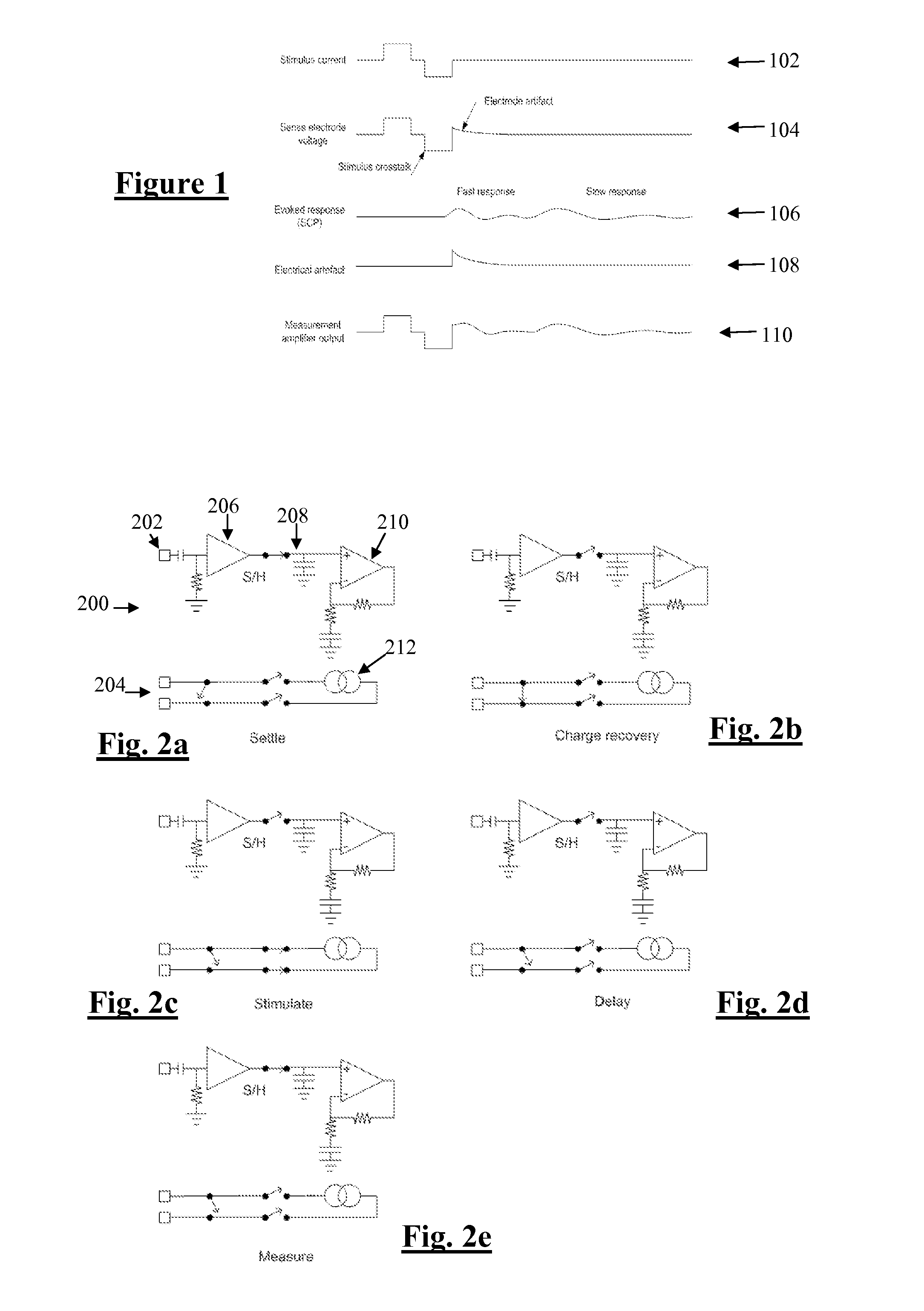
[0054]FIG. 1 shows the currents and voltages that contribute to SCP measurements. These signals include the stimulus current 102 applied by two stimulus electrodes, which is a charge-balanced biphasic pulse to provide low artefact. Alternative embodiments may instead use three electrodes to apply a tripolar charge balanced stimulus. In the case of spinal cord stimulation, the stimulus currents 102 used to provide paraesthesia and pain relief typically consist of pulses in the range of 3-30 mA amplitude, with pulse width typically in the range of 100-400 μs, or alternatively may be paraesthesia-free such as neuro or escalator style stimuli. The stimuli can comprise monophasic or biphasic pulses.

[0055]The stimulus 102 induces a voltage on adjacent electrodes, referred to as stimulus crosstalk 104. Where the stimuli 102 are SCP stimuli they typically induce a voltage 104 in the range of about 1-5 V on a SCP sense electrode.

[0056]The stimulus 102 also induces electrode artefact, which i...


PUM


Abstract

A method for measuring a neural response to a stimulus. Measurement circuitry is settled prior to a stimulus, by connecting a sense electrode to the measurement circuitry to allow the measurement circuitry to settle towards a bio-electrically defined steady state. Charge is recovered on stimulus electrodes by short circuiting the stimulus electrodes to each other. An electrical stimulus is then applied from the stimulus electrodes to neural tissue, while keeping the sense electrode disconnected from the measurement circuitry. After the stimulus, a delay is imposed during which the stimulus electrodes are open circuited and the sense electrode is disconnected from the measurement circuitry and from the stimulus electrodes. After the delay, a neural response signal present at the sense electrode is measured by connecting the sense electrode to the measurement circuitry.

Description

CROSS-REFERENCE TO RELATED APPLICATIONS[0001]This application claims the benefit of Australian Provisional Patent Application No. 2011901817 filed 13 May 2011, which is incorporated herein by reference.TECHNICAL FIELD[0002]The present invention relates to measurement of a neural response to a stimulus, and in particular relates to measurement of a compound action potential by using one or more electrodes implanted proximal to the neural pathway.BACKGROUND OF THE INVENTION[0003]Neuromodulation is used to treat a variety of disorders including chronic pain, Parkinson's disease, and migraine. A neuromodulation system applies an electrical pulse to tissue in order to generate a therapeutic effect. When used to relieve chronic pain, the electrical pulse is applied to the dorsal column (DC) of the spinal cord or dorsal root ganglion (DRG). Such a system typically comprises an implanted electrical pulse generator, and a power source such as a battery that may be rechargeable by transcutane...

Claims


Application Information

Patent Timeline
Patent Type & Authority Applications(United States)
IPC IPC(8): A61B5/04A61B5/00
CPCA61B5/04001A61B5/7285A61B5/6846A61B5/4848A61N1/36125A61N1/36135A61N1/36146A61B5/7203A61B5/24A61M5/1723A61M2230/08A61N1/36071
Inventor PARKER, JOHN LOUISSINGLE, PETER SCOTT VALLACKKARANTONIS, DEAN MICHAEL
Owner SALUDA MEDICAL PTY LTD
Why Eureka
Try Eureka